H3CA
H3CA
117
Installation
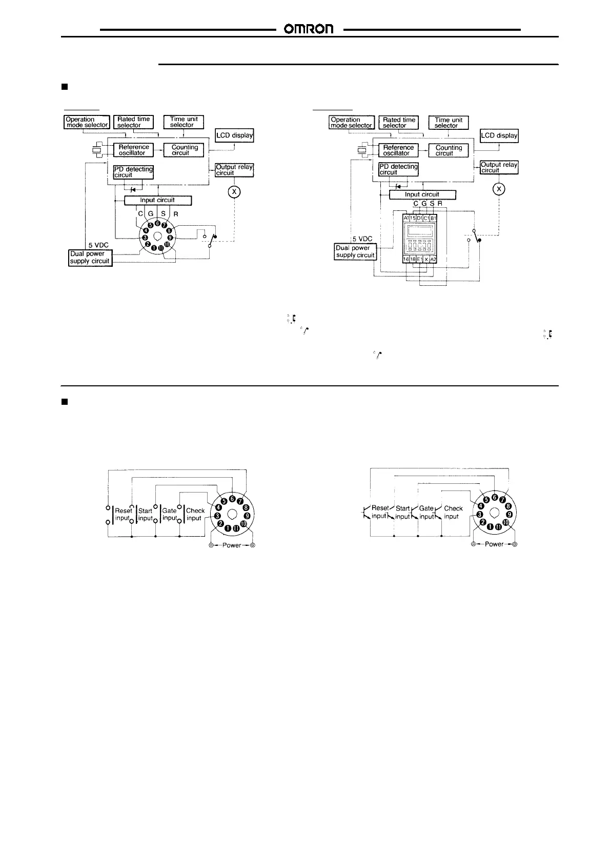
Terminal Arrangement
H3CA-A H3CA-FA
(See
note
2)
(See
note
2)
** * *
****
Note: 1. *C: Check:
C
--
D
*G: Gate:
C
--
E
*S: Start:
C
--
F
*R: Reset:
C
--
G
2. Conventional time-limit contacts are symbolized as .
However, the contacts of H3CA-A are symbolized as
because timer has 8 operation modes.
Note: 1. *C: Check: X-E1
*G: Gate: X-D1
*S: Start: X-C1
*R: Reset: X-B1
2. Conventional time-limit contacts are symbolized as .
However, the contacts of H3CA-FA are symbolized
as because timer has 8 operation modes.
(+) or
(--)
(+) or
(--)
(+)or(--)
(+)or(--)
Input Connections
Signal Inputs
Connect thestartinput contact between terminals
C
and
F
,thereset
input contact between terminals
C
and
G
, the gate input contact be-
tween terminals
C
and
E
, and the check input contact between ter-
minals
C
and
D
.
For each signal input contact, use a gold-plated contacts with high
reliability. Be sure that these input signals satisfy the following re-
quirements:aresistanceof1k
$
(max.) andaresidual voltageof1V
(max.) when the contact is made.
Solid-state Signal Inputs
Connect the start input transistor between terminals
C
and
F
,there-
set input transistor between terminals
C
and
G
, the gate input tran-
sistorbetween terminals
C
and
E
, andthe check input transistorbe-
tween terminals
C
and
D
.
For signal input, use an open collector type transistor with charac-
teristics:V
CEO
=20Vmin.,V
CE(S)
= 1 V max., IC = 50 mA min. and
I
CBO
=0.5
&
A max. In addition, be sure that the input signals satisfy
the following requirements: a resistance of 1 k
$
(max.) and a resid-
ualvoltageof 1V (max.) when thetransistor is ON, andaresistance
of 200 k
$
(min.) when the transistor is OFF.
 Loading...


