H3CA
H3CA
118
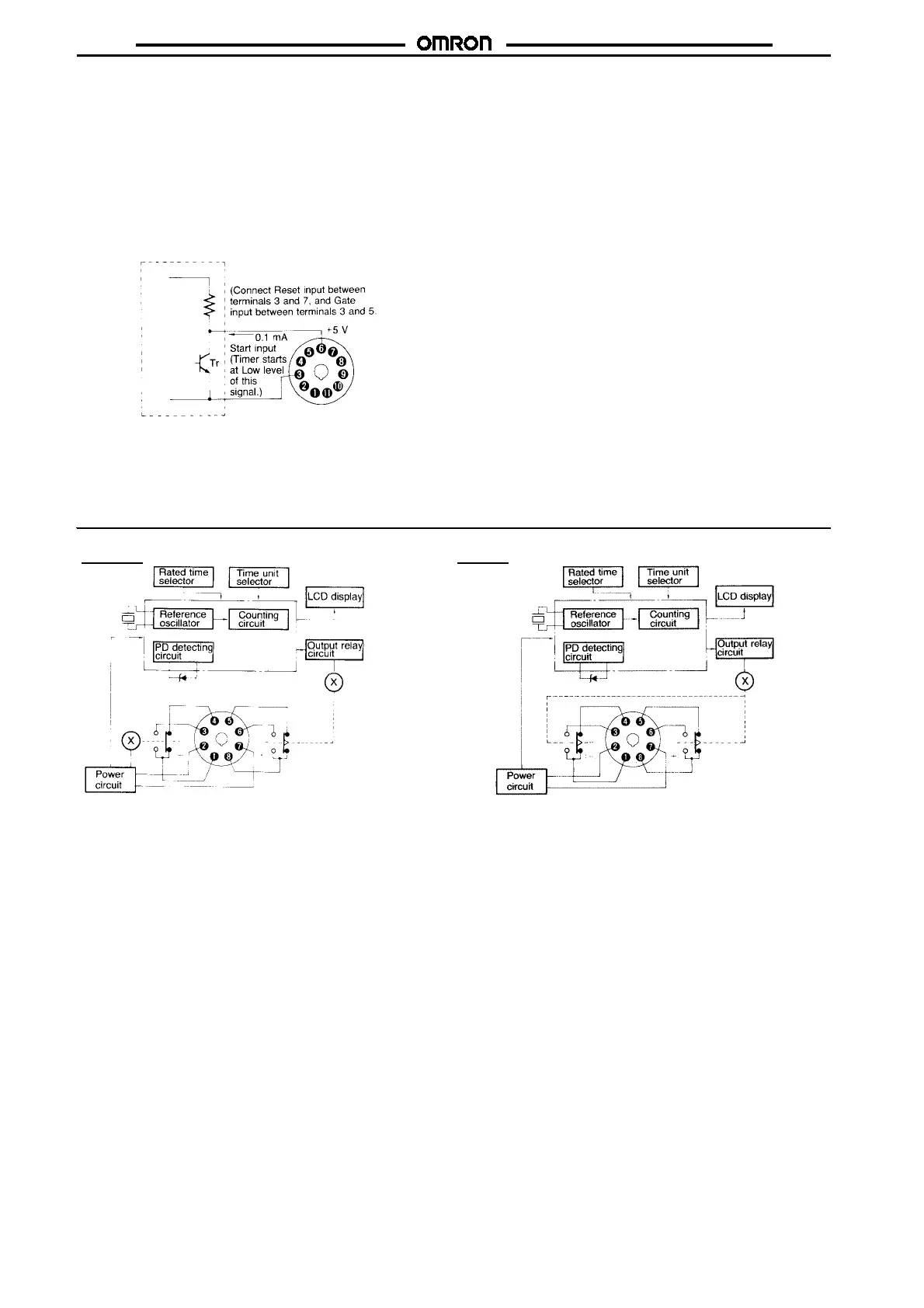
Froma solid-statecircuit (proximity sensor, photoelectric sensor,or
the like) with rated power supply voltage ranging from 6 to 30 VDC,
input signals can also be applied by other than an open collector
type transistor as shown in the following diagram. The input signal
from a solid-state circuit is applied when output transistor Tr turns
ON.Interms of signal voltage, the signalis inputwhen it goes from a
high to low level. Again, the residual voltage should be 1 V (max.)
when the transistor is ON. As the current output from the timer to Tr
isapproximately0.1mA,thisconnectionis possibleprovided there-
sidual voltage is kept to a maximum of 1 V.
Solid-state circuit (proximity sensor,
photoelectric sensor, etc.)
Note: Except for the power supply circuitry, avoid the laying of in-
put signal wires in parallel or in the same conduit with high-
tension or power lines. It is recommended to use shielded
wires or wiring with independent metal conduits for the
shortest possible distance.
H3CA-8H H3CA-8
 Loading...


