22 Multifunction Digital Timer H5CX-A/-L (Timer Function)
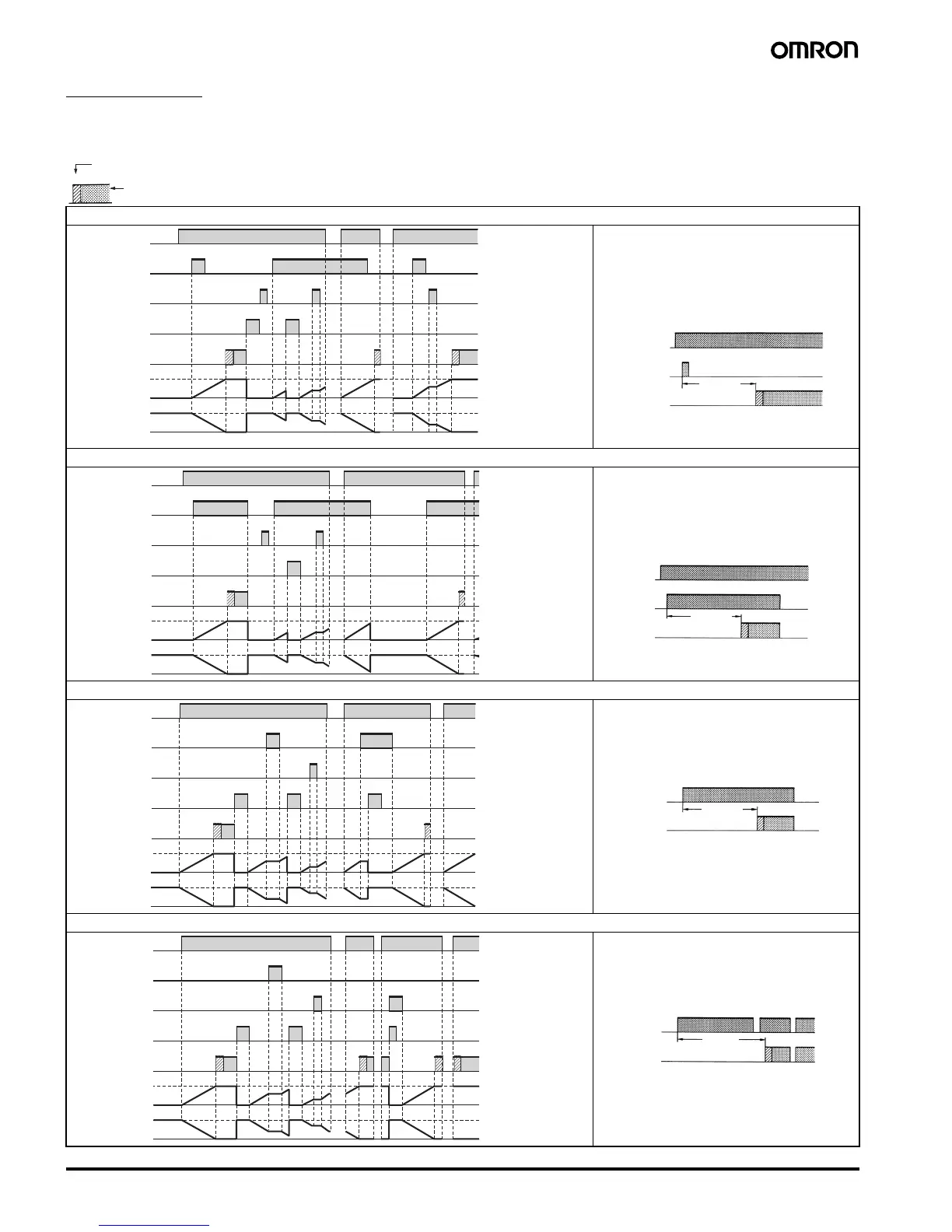
Timing Charts
Timer Operation
The gate input is not included in the H5CX-L8@ models.
Output mode A: Signal ON delay 1 (Timer resets when power comes ON.)
Output mode A-1: Signal ON delay 2 (Timer resets when power comes ON.)
Output mode A-2: Power ON delay 1 (Timer resets when power comes ON.)
Output mode A-3: Power ON delay 2 (Timer does not reset when power comes ON.)
t
Either one-shot output or sustained output can be selected.
One-shot output
Sustained output
tt
0
UP
DOWN
0
Power
Start signal
Gate
Reset
Control output
Set value
Set value
Timing
diagram
**
Basic Operation
Power
Timing
Output
Timing starts when the start signal goes ON.
While the start signal is ON, the timer starts when the
power comes ON or when the reset input goes OFF.
The control output is controlled using a sustained or
one-shot time period.
Start signal
input
*
Output is instantaneous when setting is 0.
**
Start signal input is disabled during timing.
t
UP
0
DOWN
0
Power
Start signal
Gate
Reset
Control output
Set value
Set value
Timing
diagram
*
Output is instantaneous when setting is 0.
Basic Operation
Power
Timing
Output
Timing starts when the start signal goes ON, and is
reset when the start signal goes OFF.
While the start signal is ON, the timer starts when the
power comes ON or when the reset input goes OFF.
The control output is controlled using a sustained or
one-shot time period.
Start signal
input
t
0
UP
DOWN
0
Power
Start signal
Gate
Reset
Control output
Set value
Set value
Timing
diagram
*
Output is instantaneous when setting is 0.
Basic Operation
Power
Timing
Output
Timing starts when the reset input goes OFF.
The start signal disables the timing function (i.e., same
function as the gate input).
The control output is controlled using a sustained or
one-shot time period.
ttt
0
UP
DOWN
0
Power
Start signal
Gate
Reset
Control output
Set value
Set value
Timing
diagram
* Output is instantaneous when setting is 0.
Basic Operation
Power
Timing
Output
Sustained
Timing starts when the reset input goes OFF.
The start signal disables the timing function (i.e.,
same function as the gate input).
The control output is controlled using a sustained or
one-shot time period.