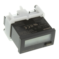
H7ET
H7ET
7
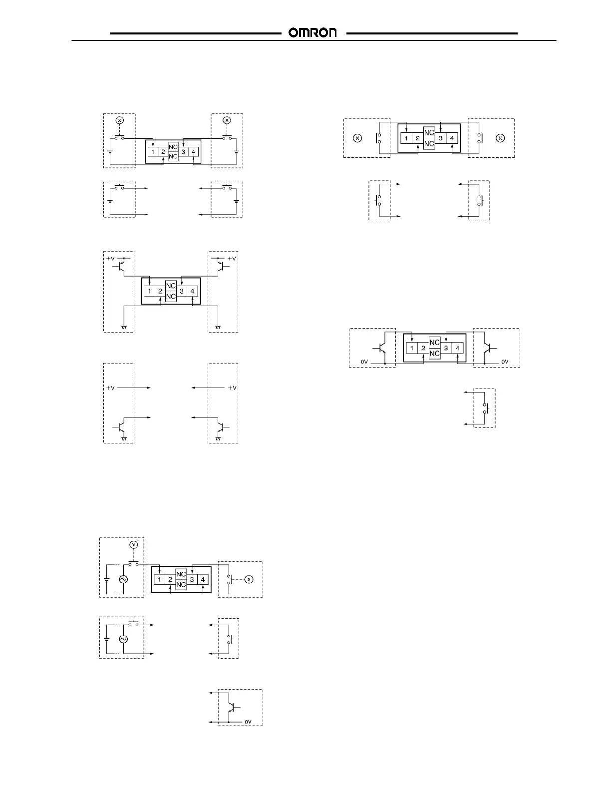
J NO-VOLTAGE INPUT MODEL
1. Contact Input (Input by a Relay or Switch Contact)
2. Solid-state Input
(Open Collector Input of an NPN Transistor)
Note: Use Relays and Switches that have high contact
reliability because the current flowing from
terminals 1 or 3 is as small as approx. 10 µA.
OMRON’s G3TA-IA/ID is recommended as the
SSR.
Note: 1. Residual voltage in the output section of Proximity
Sensors or Photoelectric Sensors becomes less
than 0.5 V because the current flowing from
terminals 1 or 3 is as small as approx. 10 µA,
allowing easy connection.
2. Select input transistors according to the following:
Dielectric strength of the collector ≧ 50 V
Leakage current < 1 µA
J AC/DC MULTI-VOLTAGE INPUT MODEL
J PNP/NPN UNIVERSAL DC VOLTAGE
INPUT MODEL WITHOUT BACKLIGHT
1. Contact Input (Input by a Relay or Switch Contact)
2. Solid-state Input
Note: 1. Terminals 2 and 4 (input circuit and reset circuit)
are functionally isolated.
2. Select input transistors according to the following:
Dielectric strength of the collector ≧ 50 V
Leakage current < 1 µA
Relay
Input
Reset
Relay
or Switch
or Switch
or Open c ollector of an
NPN transi stor
or Open c ollector of an
NPN transi stor
Open collector of a
PNP transistor
Open col lector of a
PNP transistor
Input
Reset
Relay
Relay
Input
Reset
or Switch
or Switch
or Open c ollector of
an NPN transistor
or Switch
Open collector of an
NPN transistor
Open collector of an
NPN transistor
Input
Reset
Terminals 2 and 4 are
internally connected.
Relay
Input Reset
Relay
or Switch or Swi tch
Terminals 2 and 4 are
internally connected.
 Loading...


