23180-000 Rev A Mobile Robot LD, LD-CT Assembly Instructions 31
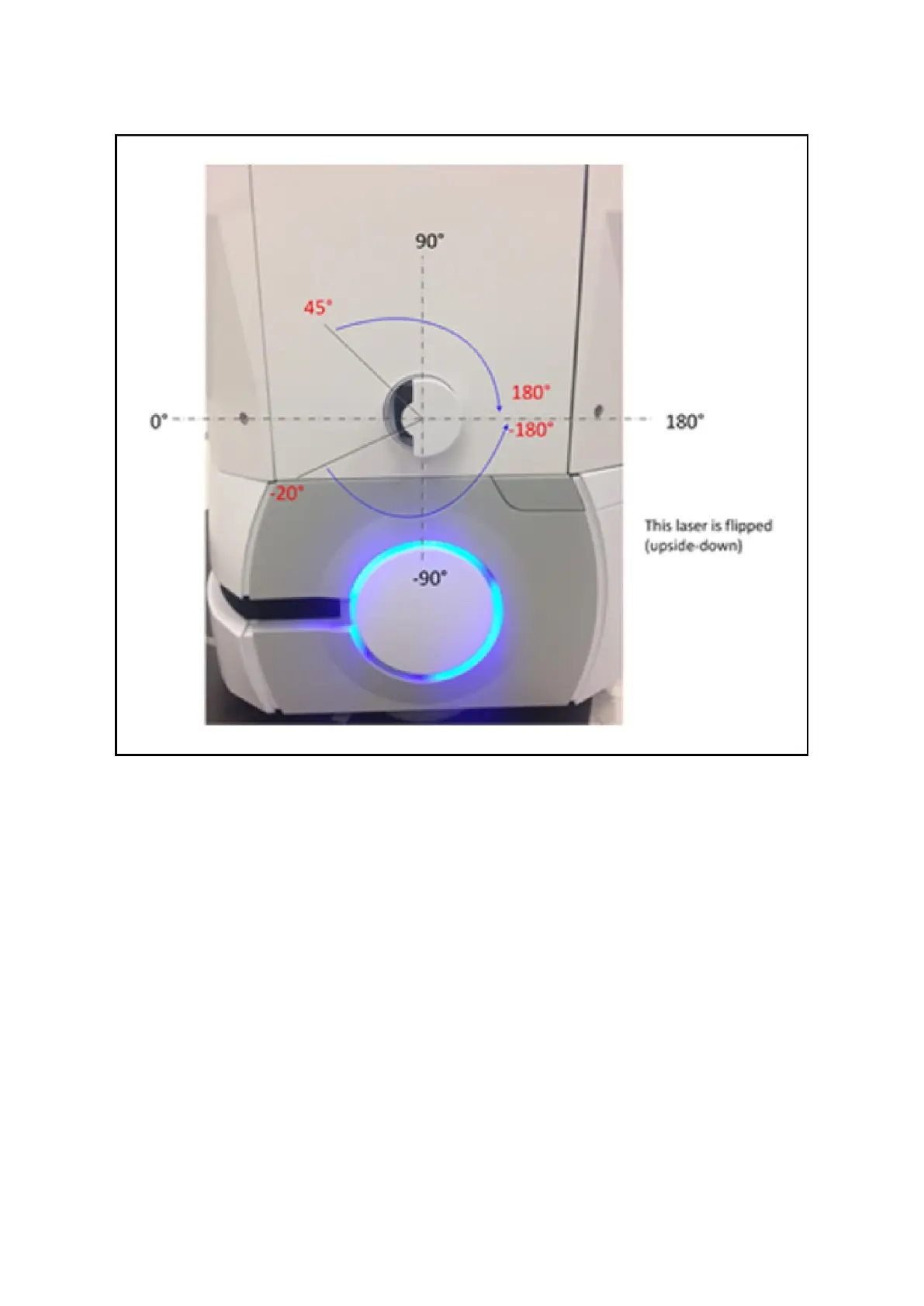
Figure 2: Left Side Laser (Laser 4)
The format for the angles is startangle1: stopangle1, startangle2: stopangle2, etc.
Readings inside these angles will be ignored.
An example would be
-20:-180,45:180
• LaserFlipped: For the laser on the left side of the robot, check the box.
This says the laser is upside-down, so the readings are interpreted correctly.
• LaserType: Set this value to tim3XX unless otherwise requested.
• LaserPortType: Set to serial when using the Aux Sensor connector.
• LaserPort: The ports available on the Aux Sensor connector are /dev/ttyUSB5 and /dev/ttyUSB6.
Assure that the correct port is designated by the sensor’s X,Y,Z position.
The wiring harness is labelled so that /dev/ttyUSB6 is connected to the left laser.
• LaserPowerOutput: Set to Vertical_Laser_Power.