2-2 Example System
2
2
Designing Systems
22 NP Introduction Manual
■ System Components
The following components are used for the shutter control system:
Display Device
• NP3-MQ000 (3-inch, 3-switch type)
• XW2Z-200T (PT-PLC connection cable)
PLC
• CP1L-L14D- (14-point I/O type)
• CP1W-CIF01 (RS-232C option board)
Equipment and Software for Programming
•PC
• USB cable (type A connector (male) - type B connector (female))
• NP-Designer (NP screen programming tool)
• CX-Programmer (PLC programming tool)
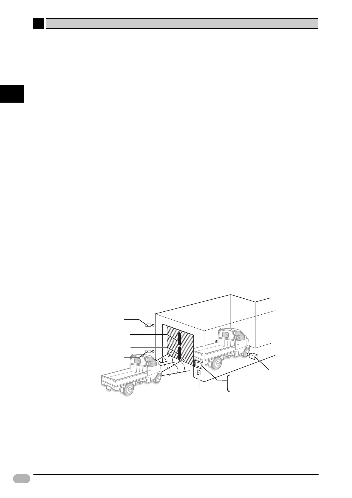
Inputs
• OPEN switch : SW1 (allocated on the NP Function Switch)
• STOP switch : SW2 (allocated on the NP Function Switch)
• CLOSE switch : SW3 (allocated on the NP Function Switch)
• Vehicle sensor : SEN1
• Light sensor : SEN2
• Limit switch, turned ON when shutter is fully open : LS1
• Limit switch, turned ON when shutter is fully closed : LS2
Outputs
• Contact for activating shutter escalation motor : MO1
• Contact for activating shutter de-escalation motor : MO2
LS1
MO1
SEN2
SW1
SW2
SW3
SEN1
LS2
MO2
 Loading...


