Appendix 4 Using NT-AL001 Converters
A-4-4 DIP Switch Settings
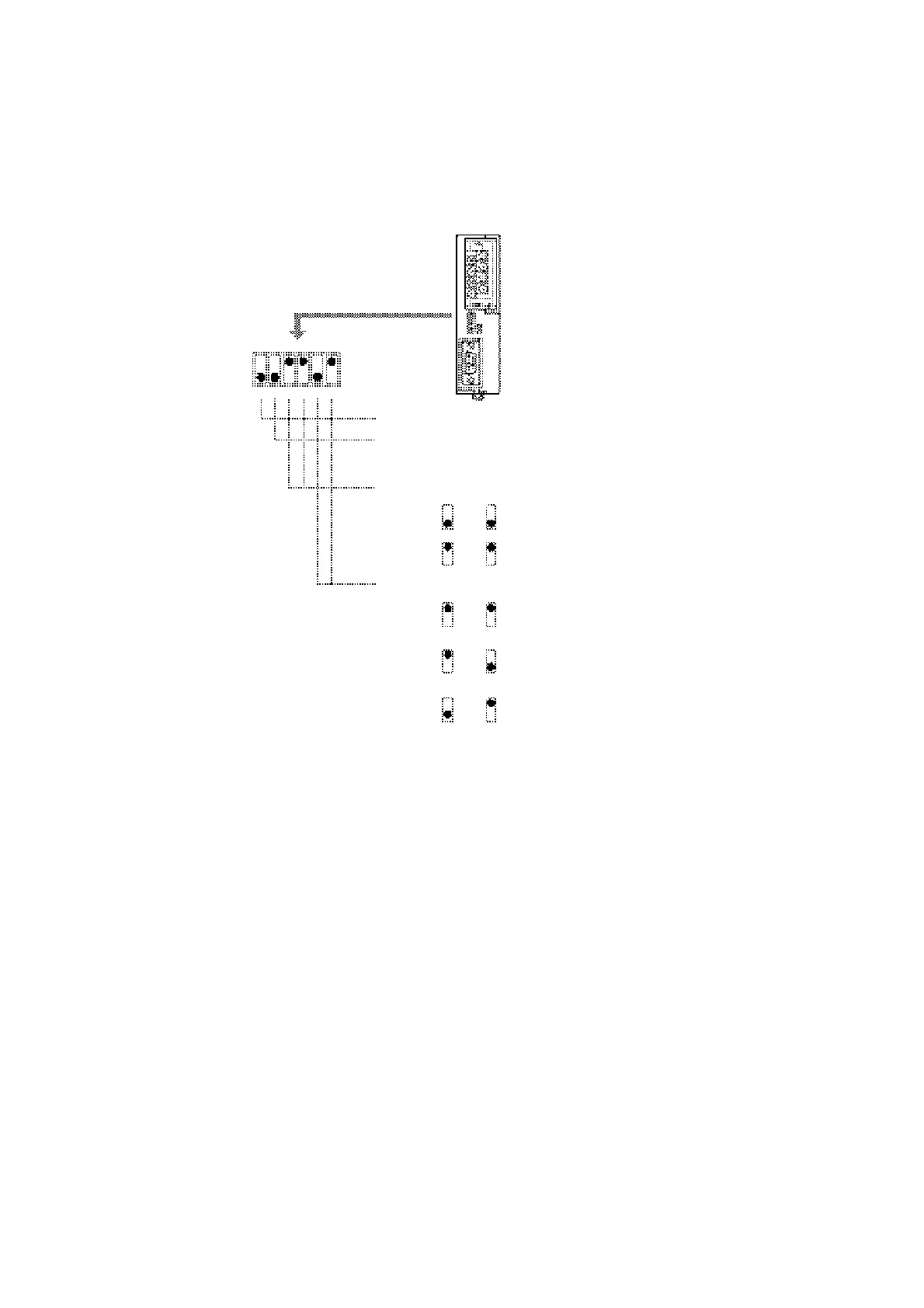
The converter unit has 6 digits DIP switch for setting the RS-422A/485 communication
conditions.
Before connecting the cable to the converter unit, make the DIP switch settings.
(Factory settings)
SW1
ON
[SW1-1]
[SW1-2]
-OFF
-ON
[SW1-3, 4]
OFF
ON
OFF
ON
[SW1-5, 6]
OFF
ON
OFF
ON
OFF
ON
Not used (always ON)
Setting for built-in terminal resistance
Terminator not set
Terminator set
Selection of 2-wire type/4-wire type
SW1-3 SW1-4
SW1-3 SW1-4
Selection of the RS-422A send mode
SW1-5 SW1-6
SW1-5 SW1-6
SW1-5 SW1-6
2-wire type (RS-485)
4-wire type (RS-422A)
Continual sending
Complies with CS control of RS-232C
(Data sent at CS high)
Complies with CS control of RS-232C
(Data sent at CS low)
1 2 3 4 5 6
When using the host link or 1:1 NT Link, set the RS-422A send mode to continual sending
(set both SW1-5 and 6 OFF).
When using the 1:N NT Link (standard or high-speed), set the RS-422A send mode to
comply with CS control of RS-232C (i.e., one of SW1-5 and SW1-6 must be ON).
Note:
•
•
•
Do not set both SW1-5 and SW1-6 ON at the same time. This may damage internal cir-
cuits.
The power supply to the device supplying +5 V must be turned OFF before starting wir-
ing work.
Before connecting the RS-232C cable and turning on the power to an RS-232C device
such as a PT (i.e., turning on the power to the converter unit), check that the cable is
wired correctly and that the DIP switch settings are correct. If the power is turned on
while there is a wiring fault, the internal circuits of the converter unit or the RS-232C de-
vice may be damaged.
A-28
 Loading...


