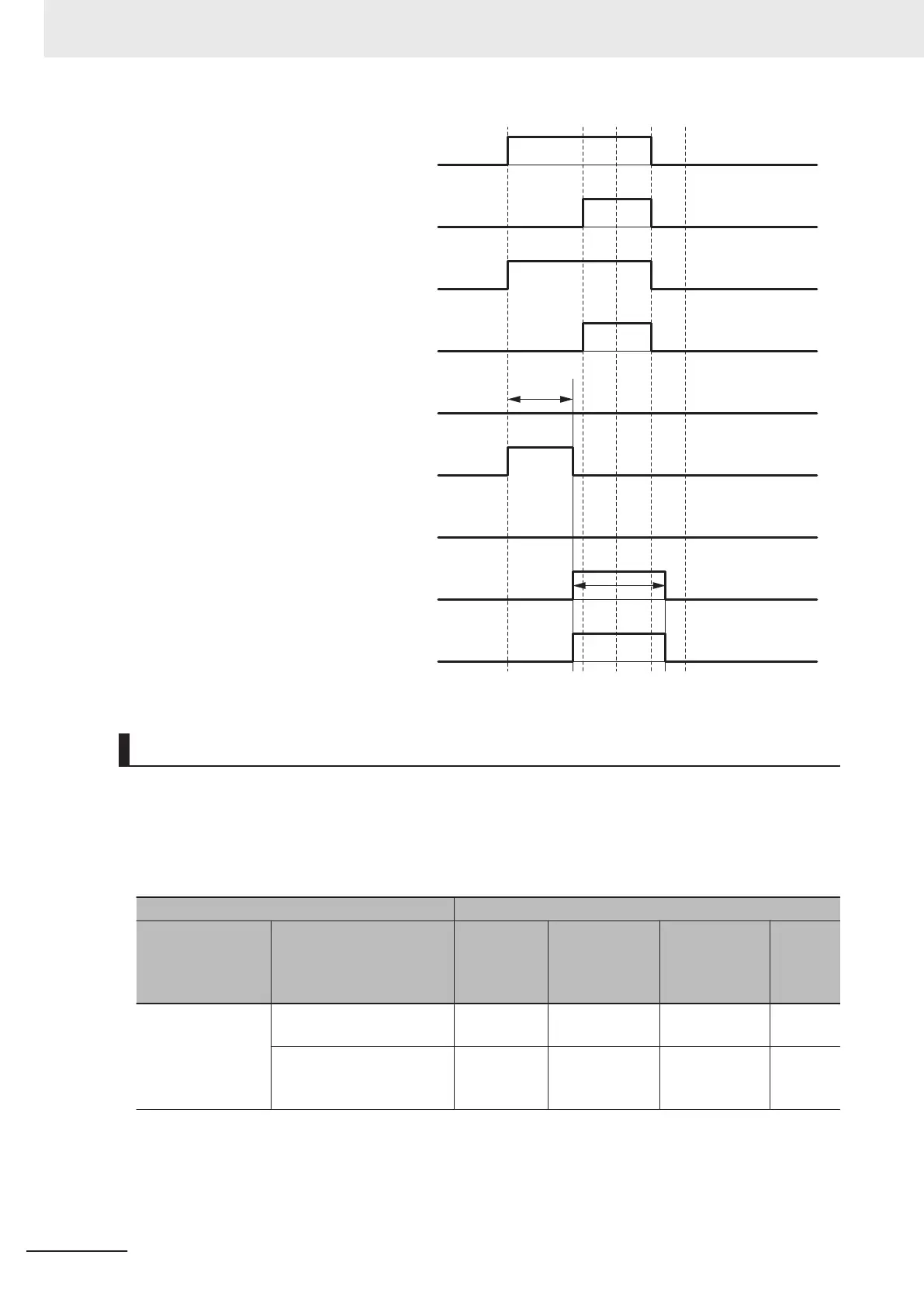
Safety input terminal 1
Safety input data 0 before dual evaluation
Safety input data 1 before dual evaluation
Safety input data 0
I/O indicator (yellow) 0
I/O indicator (yellow) 1
I/O indicator (red) 1
I/O indicator (red) 0
OFF ON OFF
Safety input terminal 0
OFF ON OFF
*1
Discrepancy
time
*1. This is the time that the error status (control data, status data, and indicator status) is held (1 s min.).
Errors Detected during Self-diagnosis
The errors that can be detected for safety input terminals are determined by the parameter settings.
The following table gives the errors that are detected for each parameter setting.
l
Devices with Mechanical Contacts and Devices with Semiconductor Out-
puts
Setting Error detection
Single/Dual Test pulse
Contact
with posi-
tive side of
power line
Ground fault
*1
Disconnection
Short
circuits
in input
wiring
Single Channel Without Test Pulse Not detecta-
ble.
Not detectable. Not detectable. ---
With Test Pulse Detectable. Detectable
when input
turns ON.
Not detectable. ---
4 Safety Control Unit Operation
4 - 28
NX-series Safety Control Unit User's Manual (Z930)
 Loading...


