Item Specification
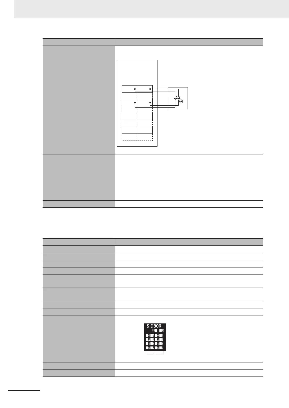
Terminal connection diagram Si0 to Si3: Safety input terminals
T0, T1: Test output terminals
Si0
Safety Input Unit
NX-SIH400
A1 B1
A8 B8
Si1
T0 T1
Si2 Si3
T0 T1
Safety Switch
Refer to 4-3-1 Safety Input Function on page 4 - 10 for details.
Installation orientation and re-
strictions
Installation orientation:
• Connected to a CPU Unit or a Communication Control Unit
*1
Possible in the upright installation orientation.
• Connected to a Communications Coupler Unit
Six possible orientations.
Restriction: Maximum ambient temperature is 50°C for any orientation oth-
er than upright installation.
Protective functions Overvoltage protection circuit and short detection (test outputs)
*1. Only NX102 CPU Units and Communication Control Units can be connected. NX1P2 CPU Units cannot be
connected.
l
NX-SID800
Item Specification
Number of safety input points 8 points
Number of test output points 2 points
Internal I/O common PNP (sinking inputs)
Rated input voltage 24 VDC (20.4 to 28.8 VDC)
OMRON Special Safety Input De-
vices
Cannot be connected.
Number of safety slave connec-
tions
1
I/O refreshing method Free-Run refreshing
External connection terminals Screwless clamping terminal block (16 terminals)
Indicators [TS] indicator, [FS] indicator, [IN] indicator, [IN ERR] indicator
[IN] indicator[I
N ERR] indicator
Safety input current 3.0 mA typical
Safety input ON voltage 15 VDC min.
2 Specifications
2 - 20
NX-series Safety Control Unit User's Manual (Z930)
 Loading...


