7
02 Technical description
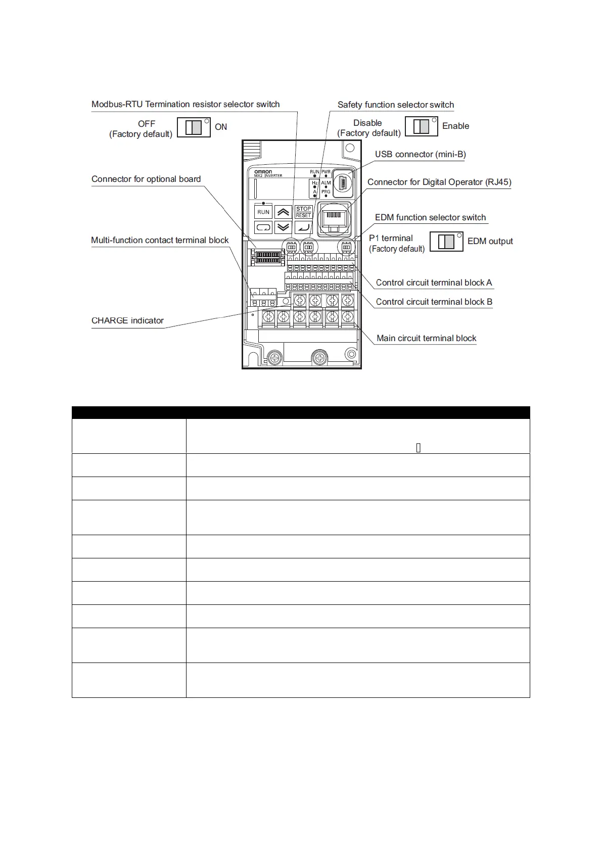
The following figure shows the designation of the parts inside the terminal block cover.
Modbus-RTU
Termination resistor
selector switch
Use this Terminal Resistor selector switch for RS-485 terminals on the control
circuit terminal
block. When this switch is turned ON, the internal 200 Resistor is connected.
Safety function selector
switch
Turn this switch ON when using the safety function. Turn OFF the power before
turning this switch ON/OFF.
EDM function
selector switch
Turn this switch ON when using the EDM output of the safety function. Turn OFF
the power cable before turning this switch ON/OFF.
Use this mini-B USB connector to connect a PC. Even when the Inverter is being
operated by a PC, etc., via USB connection, it can still be operated using the
Digital Operator.
Connector for Digital
Operator
Use this connector to connect the Digital Operator.
Connector for optional
board
Use this connector to mount the optional board. (The optional board will be
released soon.)
Control circuit terminal
blocks A and B
These terminal blocks are used to connect various digital/analog input and
output signals for inverter control.
Multi-function contact
terminal block
Use this SPDT contact terminal block for relay outputs.
Main circuit terminal
block
Use this terminal block to connect an output to the motor and Bracking Resistor,
etc. Also, use this terminal block to connect the inverter to the main power
supply.
CHARGE indicator
(Charge indicator LED)
This LED indicator is lit if the DC voltage of the main circuit (between terminals
P/+2 and N/-) remains approx. 45 V or above after the power has been cut off.
Before wiring, etc. confirm that the Charge LED indicator is turned OFF.