4-11
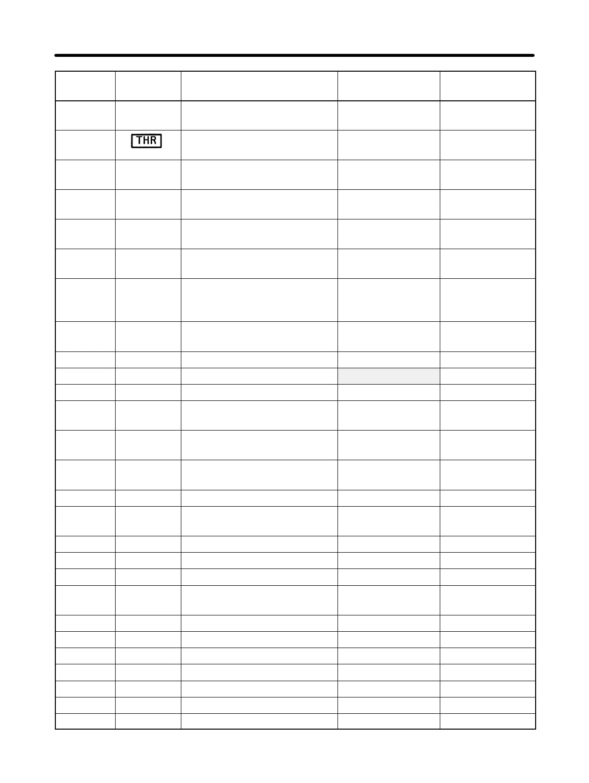
Constant
no.
Factory settingSetting rangeDescriptionDedicated
indicator
n30 Minimum output frequency
voltage
1 to 50
(see note 1)
12 (V)
(see note 1)
n31 Electronic thermal reference
current
0.0 to see note 2 See note 2
n32 Electronic thermal protec-
tion
0 to 4 0
n33 Stall prevention during de-
celeration
0, 1 0
n34 Stall prevention level during
acceleration
30 to 200 170 (%)
n35 Stall prevention level during
operation
30 to 200 160 (%)
n36 Operation after recovery
from instantaneous power
interruption
0, 1, 2 0
n37 Carrier frequency 1, 2, 3, 4
(see note 3)
4 (see note 4)
n38 Automatic torque boost gain 0.0 to 3.0 1.0
n39 Frequency reference gain 0.10 to 2.55 1.00 (times)
n40 Frequency reference bias –99 to 99 0 (%)
n41 Frequency reference upper
limit
0 to 110 100 (%)
n42 Frequency reference lower
limit
0 to 110 0 (%)
n43 Frequency reference input
terminal
0, 1 0
n44 Multi-function analog output 0, 1 0
n45 Multi-function analog output
gain
0.00 to 2.00 0.30
n46 DC control current 0 to 100 50 (%)
n47 Interruption DC control time 0.0 to 5.0 0.5 (seconds)
n48 Startup DC control time 0.0 to 5.0 0.0 (seconds)
n49 S-shape acceleration and
deceleration characteristic
0 to 3 0
n50 Over-torque detection 0 to 4 0
n51 Over-torque detection level 30 to 200 160 (%)
n52 Over-torque detection time 0.1 to 10.0 0.1 (seconds)
n53 Frequency detection level 0.0 to 400 0.0 (Hz)
n54 Slip compensation gain 0.0 to 9.9 0.0 (%)
n55 Motor current with no load 0 to 99 40 (%)
n56 Jump frequency 1 0.0 to 400 0.0 (Hz)
Preparing for Operation Chapter 4