4-12
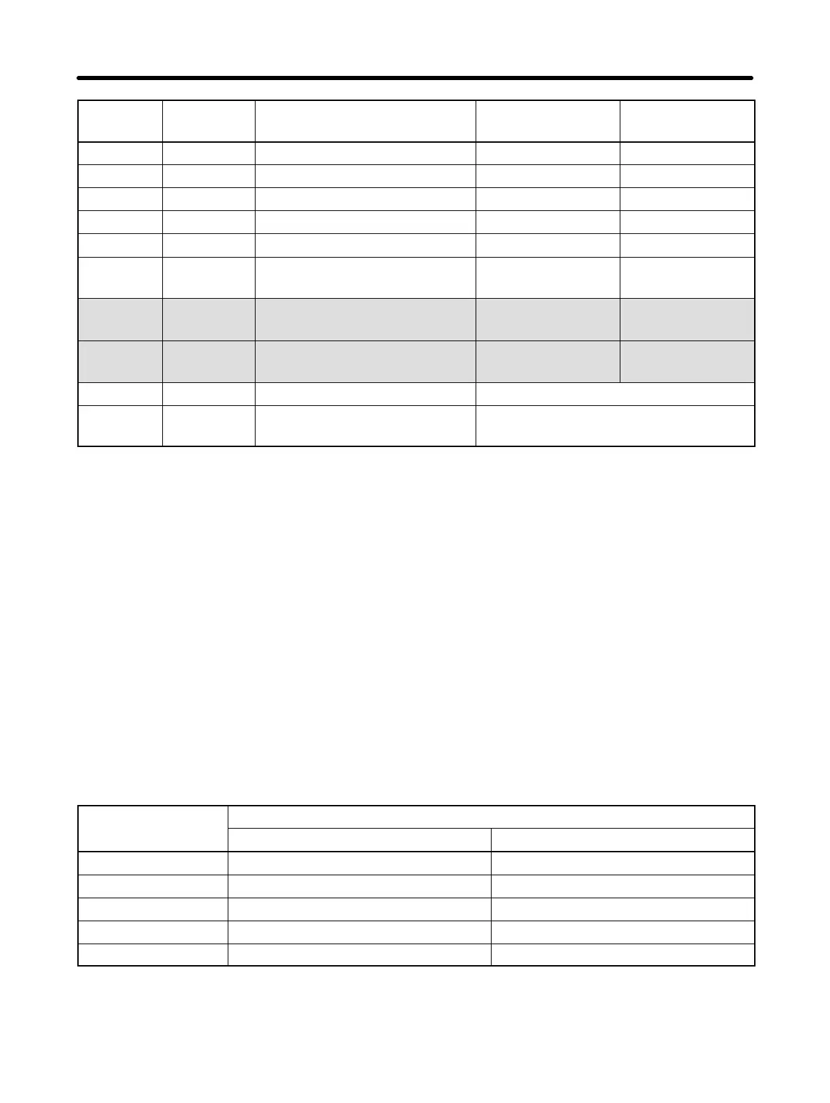
Constant
no.
Factory settingSetting rangeDescriptionDedicated
indicator
n57 Jump frequency 2 0.0 to 400 0.0 (Hz)
n58 Jump frequency 3 0.0 to 400 0.0 (Hz)
n59 Jump width 0.0 to 25.5 1.0 (Hz)
n60 Number of fault retries 0 to 10 0 (times)
n61 Stop Key selection 0, 1 0
n62 Slip compensation primary
delay time
0.0 to 25.5 2.0
n63 UP/DOWN command fre-
quency memory
0, 1 0
n64 Operator’s frequency set-
ting method
0, 1 0
n68 Error history (Display only)
n69 PROM number (for
manufacturer’s reference)
(Display only)
Note 1. The upper limit of the setting range and the factory setting for the 400-VAC class
are double the above values.
Note 2. The setting range and factory setting for n31 (electronic thermal reference cur-
rent) depend on the Inverter model. For details, refer to page 4-24.
Normally, set the rated motor amperage in n31.
Note 3. The setting range for the 400-VAC models is “1 to 5.”
Note 4. The factory setting for the 3G3EV-A4015-CUE is “3.”
Note 5. Displaying the constant no. corresponding to an indicator in the “Dedicated
indicator” column lights the indicator.
Note 6. Constant no. 02 (n02) and subsequent constants can be set only when
constant no. 01 (n01) is set to 1.
Constants in the shaded areas in the above table may not be usable depending on the
PROM number (software version). Use constant no. 69 (n69) to refer to the PROM num-
ber for the models used and make the appropriate settings.
Constant no. PROM no. (contents of n69)
219 or lower 220 or higher
n27 Setting range: 0.5 to 399 Setting range: 0.1 to 399
n29 Setting range: 0.5 to 10.0 Setting range: 0.1 to 10.0
n39 Setting range: 0.10 to 2.00 Setting range: 0.10 to 2.55
n63 No Yes
n64 No Yes
Note “Yes” indicates that the constant can be set.
“No” indicates that the constant cannot be set.
Preparing for Operation Chapter 4