2-14
Note 1. These are the cooling fan power supply and control circuit power supply input terminals.
Note 2. When 200 V is used, input 200 to 230 VAC from r – s200. When 400 V is used, input 380 to
460 VAC from r – s400.
Note 3. Do not apply DC power to the Inverters with a capacity of 55 to 160 kW. Otherwise, equipment
damage may occur.
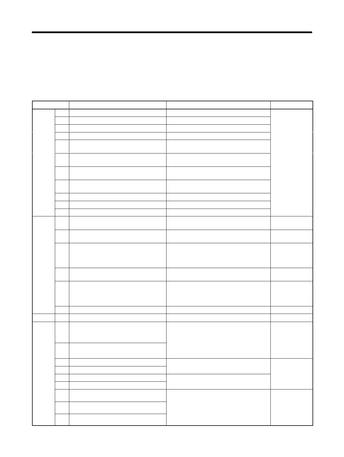
D Control Circuit Terminals for All 3G3FV-j-CE Models
Symbol Name Function Signal level
Se-
1 Forward run/Stop Forward run at ON. Stops at OFF.
Photocoupler
quence
2 Reverse run/Stop Reverse run at ON. Stops at OFF.
24 VDC, 8 mA
input
3 Multi-function contact input 1 Set by parameter H1-01 (external fault a).
4 Multi-function contact input 2 Set by parameter H1-02 (fault reset).
5 Multi-function contact input 3 Set by parameter H1-03 (multi-step refer-
ence 1).
6 Multi-function contact input 4 Set by parameter H1-04 (multi-step refer-
ence 2).
7 Multi-function contact input 5 Set by parameter H1-05 (jog frequency ref-
erence)
8 Multi-function contact input 6 Set by parameter H1-06 (external base-
block N.O.)
11 Sequence input common Common for 1 to 8.
35 Sequence switching terminal NPN/PNP input switching terminal
36 Sequence power +24V Power common for 1 to 8
Analog
input
15 Frequency reference power supply
(15 VDC)
15-VDC power supply for frequency refer-
ence.
15 VDC, 20 mA
max.
33 Frequency reference power supply
(–15 VDC)
–15-VDC power supply for frequency refer-
ence.
–15 VDC,
20 mA max.
13 Frequency reference input (voltage) Frequency reference voltage input terminal
Either 0 to +10 V or 0 to ±10 V can be se-
lected as the parameter (H3-01).
0 to 10 VDC
(20 kΩ)
0 to ±10 V
(20 kΩ)
14 Frequency reference input (current) Current input terminal for frequency refer-
ence.
4 to 20 mA
(250 kΩ)
16 Multi-function analog input Set by parameter H3-05. 0 to 10 VDC
(20 kΩ)
0 to ±10 V
(20 kΩ)
17 Frequency reference input common Common for analog input signal. ---
Shield E Shielded wire connecting ground For connecting to shielded wires ---
Se-
quence
output
9 Multi-function contact output (NO condi-
tion)
Set by parameter H2-01 (during running). Contact output
(SPST-NO)
30 VDC, 1 A
10 Multi-function contact output common
max.
250 VAC, 1 A
max.
25 Multi-function output 1
Set by parameter H2-02 (zero speed Open collector
27 Multi-function output 1 common
detection). output
26 Multi-function output 2
Set by parameter H2-03 (agree output ref-
48 V, 50 mA
max.
37 Multi-function output 2 common
erence detection).
max.
18 Fault output (NO condition)
When fault occurs: Contact output
(SPDT)
19 Fault output (NC condition)
Terminals 18 to 20: Closed
Terminals 19 to 20: Open
(SPDT)
30 VDC, 1 A
max.
20 Fault output common
max.
250 VAC, 1 A
max.
Installation Chapter 2
AUDIN - 8, avenue de la malle - 51370 Saint Brice Courcelles - Tel : 03.26.04.20.21 - Fax : 03.26.04.28.20 - Web : http: www.audin.fr - Email : info@audin.fr

 Loading...


