2-15
Symbol Signal levelFunctionName
Analog
output
21 Multi-function analog output 1 Set by parameter H4-01. (Output frequen-
cy: 0 to ±10 V/±100% frequency)
0 to ±10 VDC, 0
to 10 VDC,
23 Multi-function analog output 2 Set by parameter H4-01. (Output current:
5 V/Inverter rated current)
2 mA max.
22 Multi-function analog output common Common for analog output.
---
40
For option
41
42
43
Note The settings shown in parentheses in the “Function” column for the multi-function inputs and mul-
ti-function contact outputs indicate default settings.
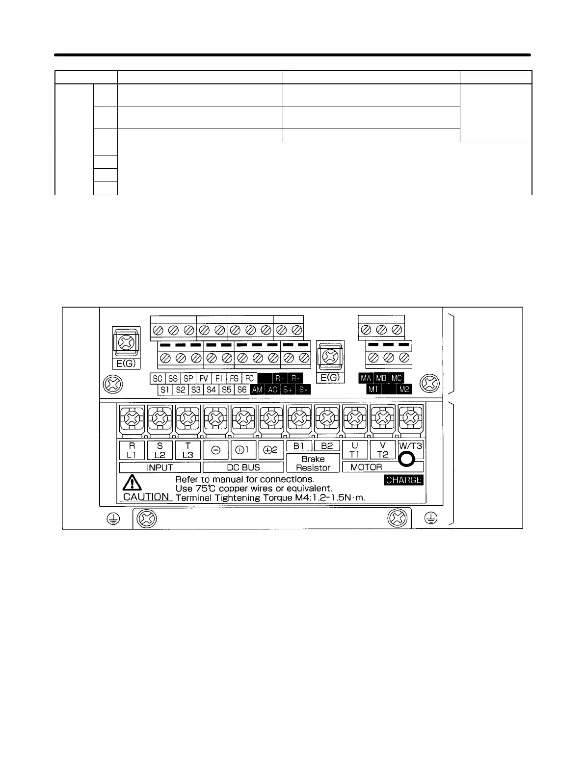
H 3G3HV Series
D Terminal Block Configuration (400-V Class with 3.7-kW Output, CE Models)
Control
circuit
terminals
Main circuit
terminals
Installation Chapter 2
AUDIN - 8, avenue de la malle - 51370 Saint Brice Courcelles - Tel : 03.26.04.20.21 - Fax : 03.26.04.28.20 - Web : http: www.audin.fr - Email : info@audin.fr

 Loading...


