1-7
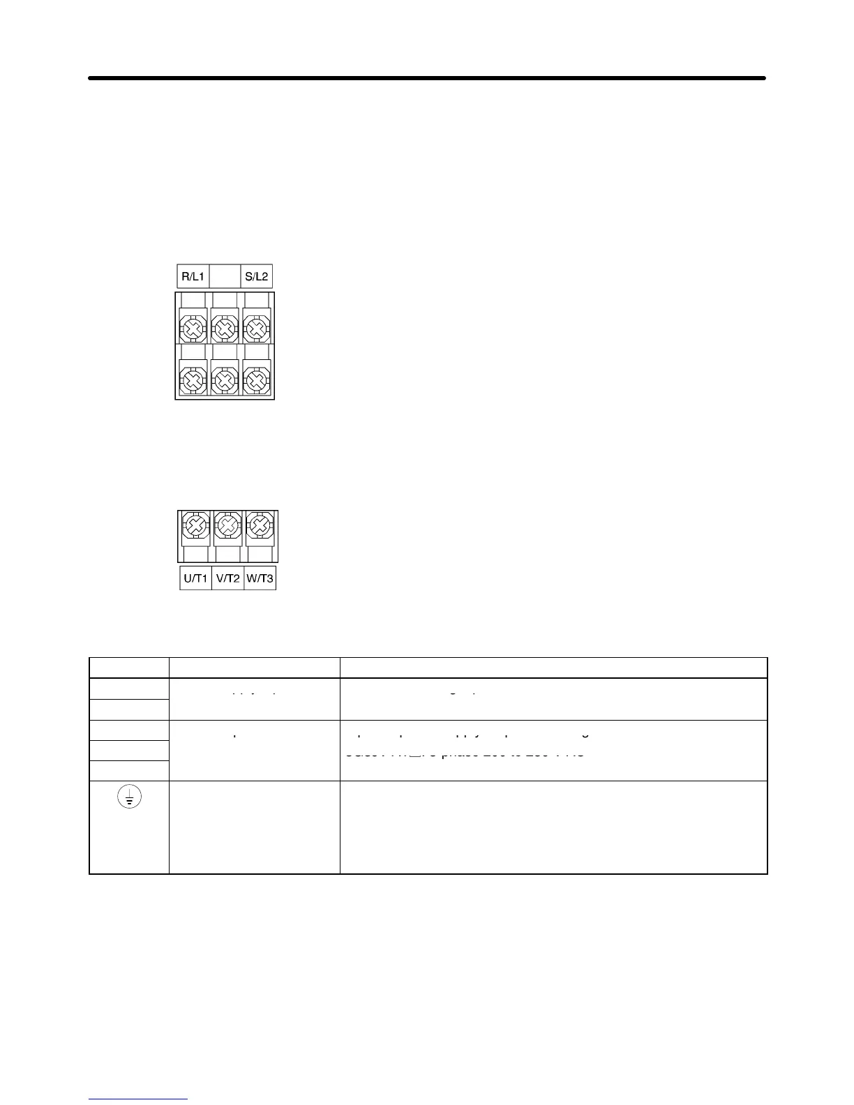
H Arrangement of Main Circuit Terminals
D 3G3JV-A1001, -A1002
Main Circuit Input Terminals
(Upper Side)
Main Circuit Output Terminals
(Lower Side)
H Main Circuit Terminals
Symbol Name Description
R/L1
Power supply input
3G3JV-A1j: Single-phase 100 to 115 V AC
S/L2
Note Connect single-phase input to terminals R/L1 and S/L2.
U/T1
Motor output terminals 3-phase power supply output for driving motors.
V/T2
3G3JV-A1j: 3-phase 200 to 230 V AC
W/T3
Ground terminal Be sure to ground the terminal under the following conditions.
3G3JV-A1j: Ground at a resistance of 100 Ω or less, and connect
to the power supply’s neutral phase to conform to EC Directives.
Note Be sure to connect the ground terminal directly to the
motor frame ground.
Note The maximum output voltage corresponds to the power supply input voltage of the Inverter.
Design Chapter 1