1-13
1-3 Specifications
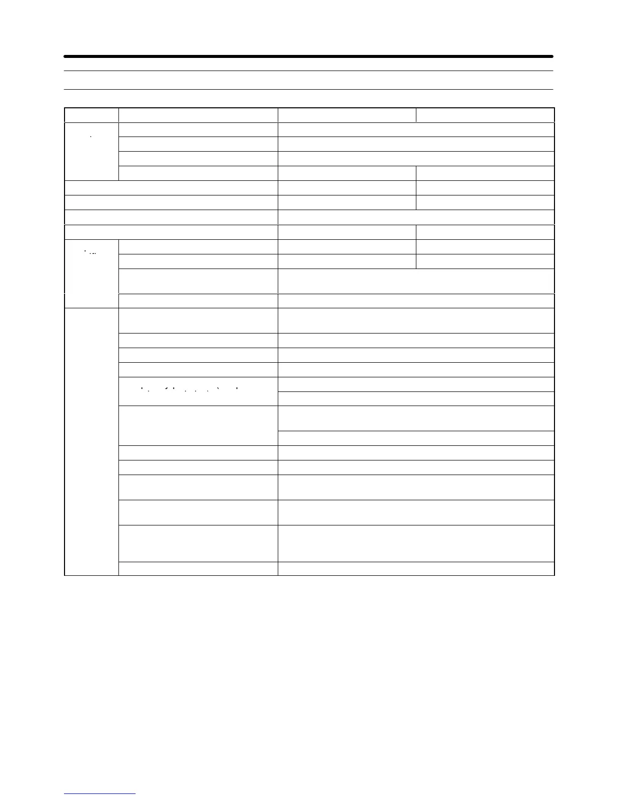
100-V AC Models 3G3JV-A1001 3G3JV-A1002
Power
Rated voltage and power supply Single-phase 100 to 115 V AC at 50/60 Hz
supply
Allowable voltage fluctuation –15 to 10%
Allowable frequency fluctuation ±5%
Input current (for rated output) (A) 3.2 6.2
Heating radiation (W) 14.6 21.1
Weight (kg) 0.5 0.8
Cooling method Natural cooling
Maximum motor capacity (kW) 0.1 0.2
Output
Rated output capacity (kVA) 0.3 0.6
Rated output current (A) 0.8 1.6
t
ons
Rated output voltage (V) Three-phase 200 to 230 V (Handles twice the input volt-
age.)
Maximum output frequency 400 Hz (Set in a parameter.)
Control
character-
Power supply harmonics counter-
measures
DC Reactor (optional) can be connected.
istics
Control method Sine wave PWM (V/f control)
Carrier frequency 2.5 to 10.0 kHz (Switched in steps.)
Frequency control range 0.1 to 400 Hz
Frequency precision (tempera-
Digital reference: ±0.01% (–10 to 50°C)
ture characteristics)
Analog reference: ±0.5% (25°C ±10°C)
Frequency setting resolution
Digital reference: 0.1 Hz (less than 100 Hz), 1 Hz (100 Hz
or greater)
Analog reference: 0.06 Hz/60 Hz (equivalent to 1/1000)
Output frequency resolution 0.01 Hz (data processing resolution)
Overload capacity 150% of rated output current for 1 min
External frequency set signal Switchable: 0 to 10 V DC (20 kΩ), 4 to 20 mA (250 Ω), 0 to
20 mA (250 Ω), or frequency adjustment
Acceleration/deceleration times 0.0 to 999 s (Acceleration and deceleration times set sepa-
rately: Switches between 2 settings.)
Braking torque Approx. 20%
Note: A Braking Resistor or Braking Resistor Unit cannot be
connected.
Voltage/frequency characteristics User-set V/f pattern
Design Chapter 1