2-6
H Example of Multi-function Display
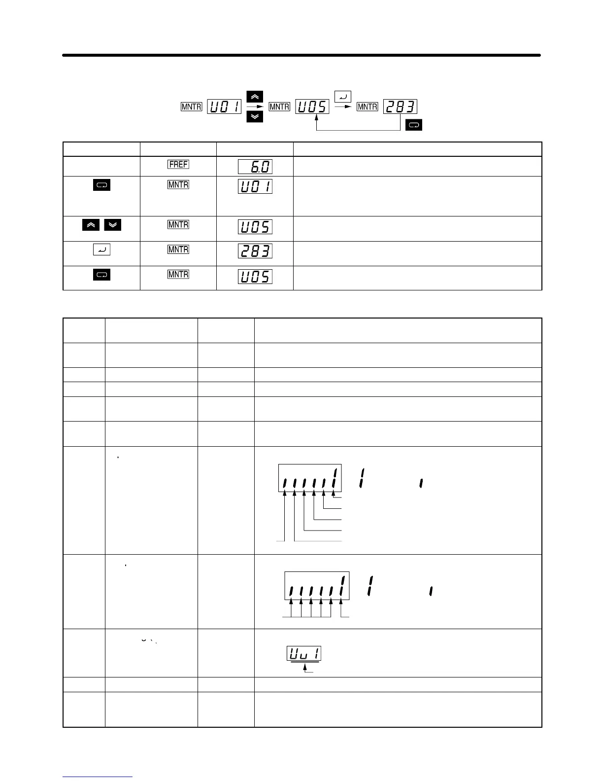
Key sequence Indicator Display Explanation
Power On
Press the Mode Key repeatedly until the MNTR
indicator is lit.
U01 will be displayed.
Use the Increment or Decrement Key to select the
monitor item to be displayed.
Press the Enter Key so that the data of the selected
monitor item will be displayed.
The monitor number display will appear again by
pressing the Mode Key.
D Status Monitor
Item Display Display
unit
Function
U01 Frequency
reference
Hz Monitors the frequency reference. (Same as FREF)
U02 Output frequency Hz Monitors the output frequency. (Same as FOUT)
U03 Output current A Monitors the output current. (Same as IOUT)
U04 Output voltage V Monitors the internal output voltage reference value of the
Inverter.
U05 DC bus voltage V Monitors the DC voltage of the internal main circuit of the
Inverter.
U06 Input terminal ---
Shows the ON/OFF status of inputs.
status
: Input ON : No input
Not
used
Terminal S1: Forward/Stop
Terminal S2: Multi-function input 1 (S2)
Terminal S3: Multi-function input 2 (S3)
Terminal S4: Multi-function input 3 (S4)
Terminal S5: Multi-function input 4 (S5)
U07 Output terminal ---
Shows the ON/OFF status of outputs.
recent one)
Error
U10 Software No. --- OMRON use only.
U15 Receive data error --- The cause of the receive data error during MEMOBUS
communications can be checked. (Same as the contents of
communications register number 003DM.)
Preparing for Operation and Monitoring Chapter 2