.
Note 1. Separate the control signal wiring from power lines.
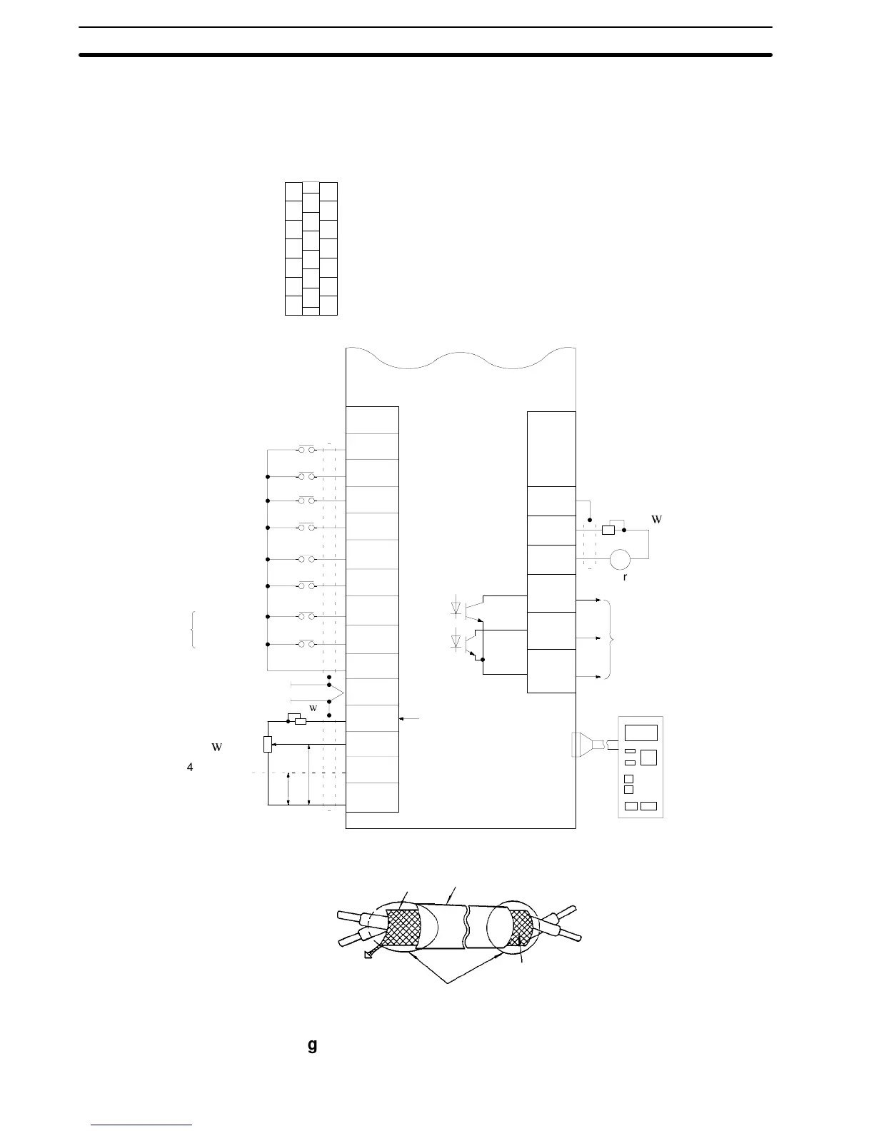
2. Use shielded leads or twisted-pair shielded leads for freq. set-
ting signal (analog) and ensure sufficient terminal processing.
Control Circuit Terminal Arrangement
1
2
3
4
5
6
7
8
9
10
11
12
13
14
15
16
17
18
19
20
1
2
3
4
5
6
7
8
9
20
10
13
11
12, 17
(20)
18
19
14
15
16
FM
P
P
Terminal
no.
Input signal
Output signal
Terminal
no.
+--
Forward run/stop
Reverse run/stop
External fault
Fault reset
Multi-step
speed setting 1
Multi-step
speed setting 2
Multi-function
contact output
Inching
operation
Accel/decel
time change
Freq. setter
2k
4to20mA
current input
Sequence
common
Shielded lead
connection terminal
+12 V
Analog
(0 V)
3G3SV
Freq. meter
calibration resistor:
RV 30YN20S
20 k
Freq. meter or current
meter 3 V 1 mA moving-
coil type
PHC output less than
48 V 50 mA
Digital operator (optional)
Shielded sheath
Armor
Never connect
Insulate these parts
with insulating tape.
To inverter shielded
sheath terminal (20)
2k
Fig. 4 Shielded Lead Termination
Section 1-4