/
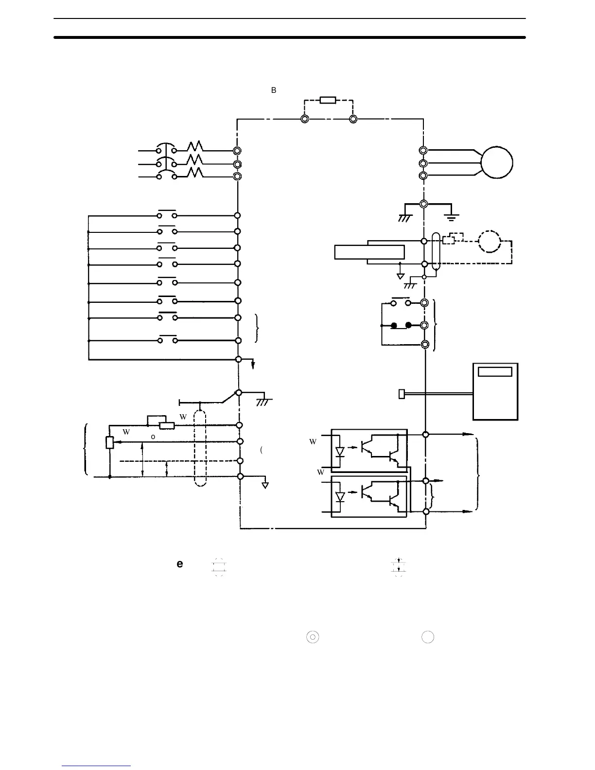
1-8-2 Connection Diagram
3-phase power supply 200/208/220 VAC,
50 Hz 200/208/220/230 VAC, 60Hz only
terminals L1 (R) and L2 (S) for
single-phase power supply
L1 (R)
L2 (S)
L3 (T)
L1 (R)
L2 (S)
L3 (T)
T1 (U)
T2 (V)
T3 (W)
IM
Fault contact output
contact capacity: less
than 1 A for 250 VAC
and 30 VDC
Analog output output
freq. 0 to +10 VDC.
Digital
operator
(optional)
Master
speed
freq.
com-
mand
MultI-func-
tion output
open col-
lector less
than 48 V
50 mA
MCCB
B1 B2
PP
4 to 20mA
Multi-function contact input
Sequence common terminal (0 v)
Open
collector 1
Shielded lead connection
terminal
Forward run/stop
Reverse run/stop
External fault input
Fault reset
Multi-step speed
setting 2
1
2
3
4
5
6
7
8
9
Multi-step speed
setting1
Jog operation
Accel/decel time
change
FM
14
15
16
Analog monitor
Open
collector 2
FLT-A
FLT-B
FLT-C
19
18
(20)
G(E)
20
10
13
11
12
17
0V
Power supply for speed setting;
+12 V 20 mA
Master command
0to10v(20k
(voltage command)
Master command
4to20mA(250
)
Braking resistor(optional, see note 4)
2k
0to+10V
(current
command)
3G3SV
2k
Note
1.
indicates shielded leads and
P
twisted-pair shielded
leads.
2. External terminal (10) of +12 V has maximum output current
capacity of 20 mA.
3. Terminal symbols: shows main circuit; shows control cir-
cuit.
4. Set overload relay when using braking resistor (type 3G3IV-
PERF150WJ).Also,use sequencer tobreakpowersupply side
on overload relay trip contact when using braking resistor or
braking resistor unit.
Section 1-8