&
Control Circuit
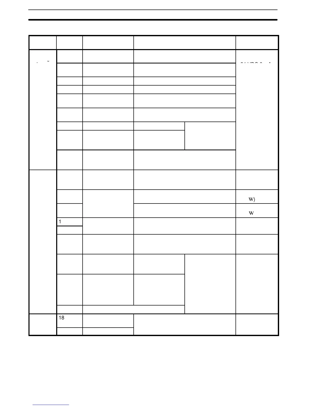
Classifi-
cation
Terminal Signal function Description Signal level
Sequence
input sig-
1 Forward operation-
stop signal
Forward run at “closed”, stop at “open”
Photocoupler in-
sulation input
nal
2 Reverse operation-
stop signal
Reverse run at “closed”, stop at “open”
+24 VDC 8 mA
3 External fault input Fault at “closed”, normal at “open”
4 Fault reset input Reset at “closed”
5 Multi-step speed ref.
1
Effective at “closed”
6 Multi-step speed ref.
2
Effective at “closed”
7 Jog command Jog run at “closed”
Multifunction contact
8 Accel/decel time se-
lect
Second accel/decel
time effective at
“closed”
input: two signals
available to select
9 Sequence control
input common termi-
nal
---
Analog in-
put signal
10 Power supply termi-
nal for speed ref.
Speed ref. power supply +12 V (allowable
current 20 mA
max.)
13 Frequency ref. 0 to +10 V/100% freq. 0to+10V
(20 k
)
11 4 to 20 mA/100% freq. 4to20mA
(250
)
12
Common terminal
0V ---
17
for control circuit
20 Connection to shield
sheath of signal
lead
--- ---
14 During running Closed between ter-
minal 14 and 16
during running
Multifunction contact
output: two signals
available to select
Open collector
output +48 V
50 mA or less
15 Frequency agreed
signal
Closed between ter-
minals 15 and 16
when set freq. =
output freq. is ob-
tained.
16 Open collector output common
Analog
output
18 Frequency meter 0 to 10 V/100%
Possible to select current meter output.
0to11Vmax.
2mAorless
signal
19 Common
Section 1-8