46
Instruction
0000 0001
0002 0003
Address Instruction Operands
000 LD 0000
001 AND NOT 0001
002 LD 0002
003 AND 0003
004 OR LD ---
Naturally, some diagrams will require both AND LOAD and OR LOAD instruc-
tions.
To code diagrams with logic block instructions in series, the diagram must be
divided into logic blocks. Each block is coded as normal using a LOAD in-
struction to code the first condition, and then AND LOAD or OR LOAD is
used to logically combine the blocks. First input the first two logic blocks and
then the logic block instruction to combine the results. Then input each addi-
tional logic block along with the logic block instruction required to combine it
with the previous result. Examples are given next.
The following diagram requires AND LOAD to be converted to mnemonic
code because three pairs of parallel conditions lie in series.
0000 0002 0004
0001 0003 0005
0100
Address Instruction Operands
000 LD 0000
001 OR NOT 0001
002 LD NOT 0002
003 OR 0003
004 AND LD —
005 LD 0004
006 OR 0005
007 AND LD —
008 OUT 0100
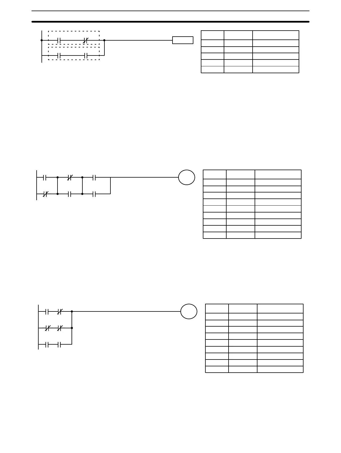
The following diagram requires OR LOAD instructions to be converted to
mnemonic code because three pairs of conditions in series lie in parallel to
each other. The first of each pair of conditions is converted to LOAD with the
assigned bit operand and then ANDed with the other condition. The first two
blocks are coded first, followed by OR LOAD, the last block, and another OR
LOAD.
0000 0001
0002 0003
00040 0005
0101
Address Instruction Operands
000 LD 0000
001 AND NOT 0001
002 LD NOT 0002
003 AND NOT 0003
004 OR LD —
005 LD 0004
006 AND 0005
007 OR LD —
008 OUT 0101
AND LOAD and OR LOAD can naturally be used in the same section of pro-
gram. The following diagram contains only two logic blocks as shown. It is
not necessary to further separate block b components, because it can coded
directly using only AND and OR.
Logic Block Instructions in
Series
Combining AND LOAD and
OR LOAD
Basic Programming Section 3-4