47
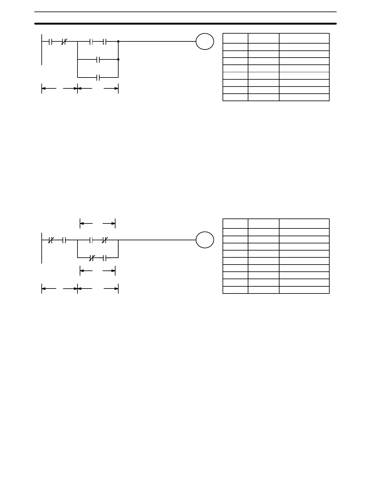
0000 0001 0002 0003
0201
0101
0004
Block
a
Block
b
Address Instruction Operands
000 LD 0000
001 AND NOT 0001
002 LD 0002
003 AND 0003
004 OR 0201
005 OR 0004
006 AND LD —
007 OUT 0101
Although the following diagram is similar to the one above, block b in the dia-
gram below cannot be coded without separating it into two blocks combined
with OR LOAD. Here the three logic blocks are coded first followed by the
two logic block instructions required to combine them. When coding the logic
block instructions together at the end of the logic blocks they are combining,
they must, as shown below, be coded in reverse order, i.e., the logic block
instruction for the last two blocks is coded first, followed by the one to com-
bine the execution condition resulting from the first logic block instruction and
the execution condition of the logic block third from the end, and on back to
the first logic block that is being combined.
0000 0001 0002 0003
0102
0004 0104
Block
a
Block
b
Block
b2
Block
b1
Address Instruction Operands
000 LD NOT 0000
001 AND 0001
002 LD 0002
003 AND NOT 0003
004 LD NOT 0004
005 AND 0104
006 OR LD —
007 AND LD —
008 OUT 0102
When determining what logic block instructions will be required to code a dia-
gram, it is sometimes necessary to break the diagram into large blocks and
then continue breaking the large blocks down until logic blocks that can be
coded without logic block instructions have been formed. These blocks are
then coded, combining the small blocks first, and then combining the larger
blocks. Either AND LOAD or OR LOAD is used to combine the blocks, i.e.,
AND LOAD or OR LOAD always combines the last two execution conditions
that existed, regardless of whether the execution conditions resulted from a
single condition, from logic blocks, or from previous logic block instructions.
When working with complicated diagrams, blocks will ultimately be coded
starting at the top left and moving down before moving across. This will gen-
erally mean that, when there might be a choice, OR LOAD will be coded be-
fore AND LOAD.
The following diagram must be broken down into two blocks and each of
these then broken into two blocks before it can be coded. As shown below,
blocks a and b require an AND LOAD. Before AND LOAD can be used, how-
Complicated Diagrams
Basic Programming Section 3-4