Wiring Section 2-2
44
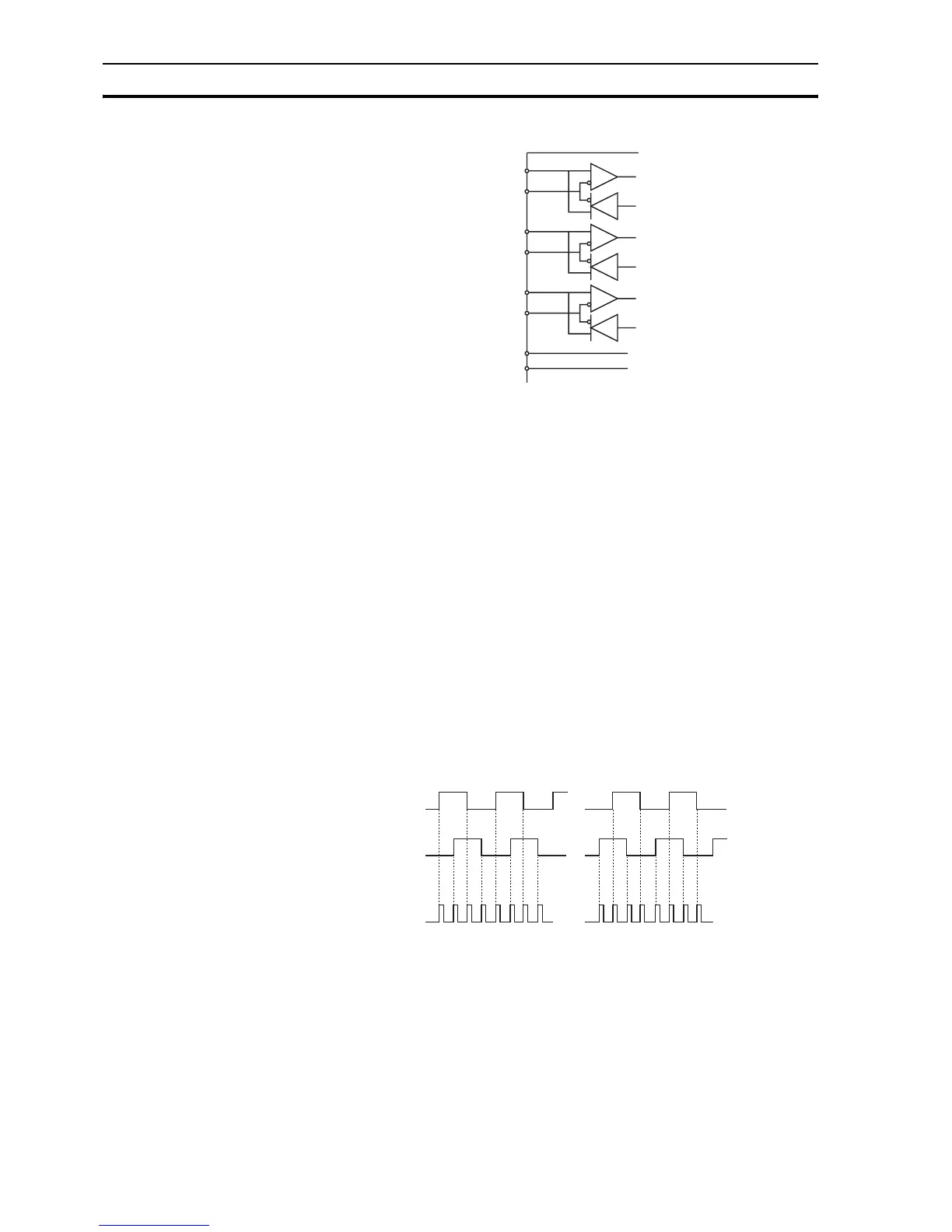
Circuit configuration for the encoder interface
2-2-3 Incremental encoder
An incremental encoder has the following phase definition:
• An advanced phase A for forward rotation.
• An advanced phase B for reverse rotation.
By monitoring the relative phase of the 2 signals, you can easily detect the
rotation direction. If signal A leads signal B, the movement is clockwise and
the counter increments. If channel B leads channel A, the movement is
counterclockwise and the counter decrements.
Most rotary encodes also provide an additional Z marker. This Z marker is a
reference pulse within each revolution. With these 3 signals, you can
determine the direction, the speed and the relative position.
2-2-3-1 Encoder input
The pulse ratio of the CJ1W-MCH72 is 1: every encoder edge (i.e., a pulse
edge for either phase A or B) is equal to one internal count.
Encoder edges
The figure shows phase A (A), phase B (B) and the number of counts (C) for
forward or clockwise rotation (D) and reverse or counterclockwise rotation (E).
The signals A, B and Z appear physically as A+ and A-, B+ and B- and Z+ and
Z-. They appear as differential signals on twisted-pair wire inputs. This makes
sure that common mode noise is rejected. When you use an encoder from
other manufacturers, check the encoder specification for the phase
+5V
0V
+5V
0V
2
A+ /
STEP+ /
...
A- /
STEP- /
...
B+ /
DIR+ /
...
B- /
DIR- /
...
Z+ /
ENA+ /
...
Z- /
ENA- /
...
3
4
5
7
8
6
9
CJ1W-MCH72
D
7766554433221100
A
B
C
E
 Loading...


