Wiring Section 2-2
45
advancement carefully. If the phase definition is different from the phase
definition of the standard OMRON equipment, reverse the B-phase wiring
between the CJ1W-MCH72 and the encoder.
2-2-3-2 Registration
When using the incremental encoder interface of the CJ1W-MCH72, the
CJ1W-MCH72 can capture the position of the Flexible Axis in a register when
an event occurs. The event is called the print registration input. On the rising
or falling edge of an input signal (either the Z marker or one of the first 2 digital
inputs), the CJ1W-MCH72 captures the position of the axis in the hardware.
You can use this position to correct possible errors between the actual position
and the desired position.
To set up the print registration, you can use the REGIST command. The
position is captured in the hardware, which means that there is no software
overhead. Therefore, you do not have to deal with timing issues.
For more information on how to use the registration inputs, refer to the
REGIST command in section 4-2-200.
2-2-3-3 Hardware PSWITCH
The MCH72 has one output (output 8) that can be used as a hardware
position switch. This output goes on when the measured position of the
Flexible Axis is reached. It goes off when another measured position is
reached.
The output is driven by hardware only. This means that the response times do
not have software delays. For more information on using the position switch,
refer to section 4-2-130 on the HW_PSWITCH command.
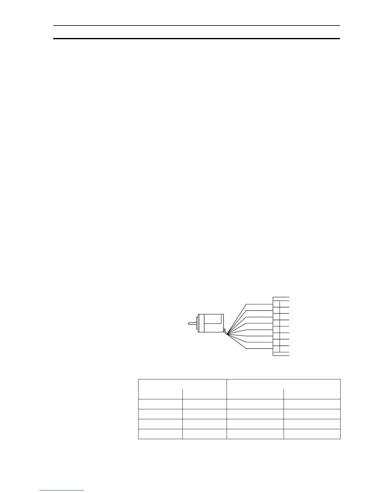
2-2-3-4 Connection example
The table below and the figure give an example of the OMRON E6B2-CWZ1Z
encoder connected to the CJ1W-MCH72.
Encoder input connection
/i
Note The encoder interface of the CJ1W-MCH72 does not have termination inside. In case
of long distances or disturbed communication, add external termination to the interface.
E6B2-CWZ1Z encoder CJ1W-MCH72 encoder interface
Signal Wire color Pin Signal
A+ Black 2 A+
A- Black/red 3 A-
B+ White 4 B+
B- White/red 5 B-
2
3
4
5
7
8
9
A+
CJ1W-MCH72
A-
B+
B-
Z+
Z-
0 V (COM)
5 VDC
6
 Loading...


