63
Appendix D - PLC/Touchscreen Connection Examples
V520-LHA7127
Appendix D
PLC Connection Examples for Serial Trigger
Sysmac PLC Series CPM2A, CPM2C, CJ1, CS1 (with serial ports providing 5V)
■ Operation
Switch ON trigger switch (6), shown above to execute
V550 to read and send data to data memory of PLC.
Use program console (5) to confirm the date.
■ V500-LPx5627-P Setup
• Communication condition (setup)
Baud rate: 9600 bps
Word length: 7 bits
Parity: Even
Stop bit: 2 bits
• Trigger Requirements
Start command Z (fixed)
■ PLC Setup
• Communication condition
Set serial port for RS-232C (no protocol)
• Setting start code
Place the number SA00 into DM100
• Connection of trigger switch
Connect a normally open switch to input
0000.00 of the input module to be able to
initiate the BCR
• BCR data will be placed in data memory starting
at DM200
Note For multidrop RS422/485 connections, use
K3SC converter at each BCR and set each BCR
with unique prefix.
■ Confirmation of Operation
• After programming, set the PLC to run on moni-
tor mode.
• Press the keys below in order if <password> is
displayed.
(1) CLR →
(2) MONTR → (3) → CLR → (4) CLR
• To see BCR data on program console:
(1) CLR → (2) FUN → (3) MONTR
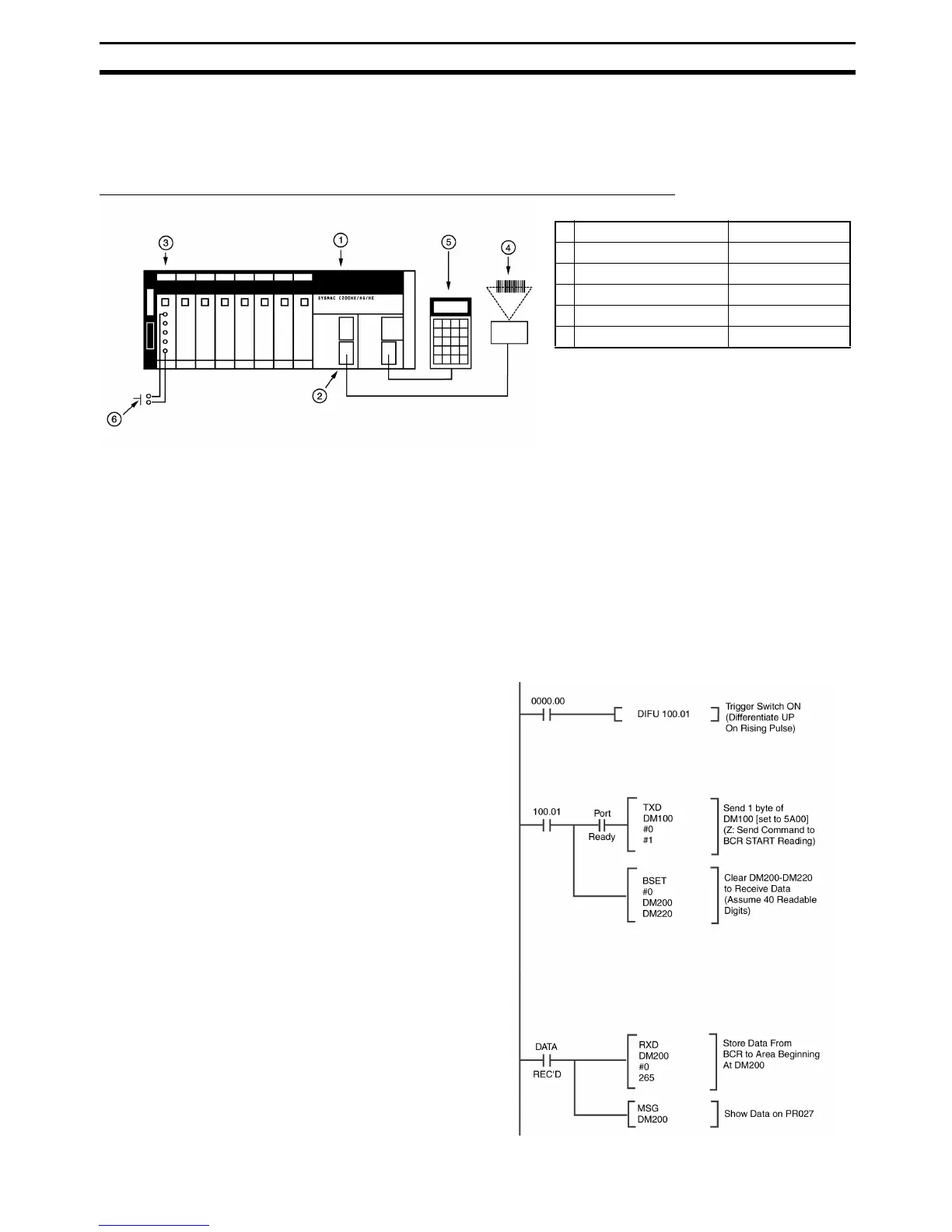
■ PLC Programming
1 CPU unit CS1G/H - CPU xx
2 PLC serial port Built into CPU
3 Input module C200H-ID xxx
4 Bar code reader V500-LPx5627-P
5 Programming console C200H-PR027-E
6 Trigger switch -
 Loading...