5 I/O Addressing ZEN Programmable Logic Module
OMRON ELECTRONICS, S.A. Page 14
5. I/O Addressing
The following tables show the I/O addressing, work areas, internal holding bits,
Timers, Counters and ZEN intelligent control screen bits.
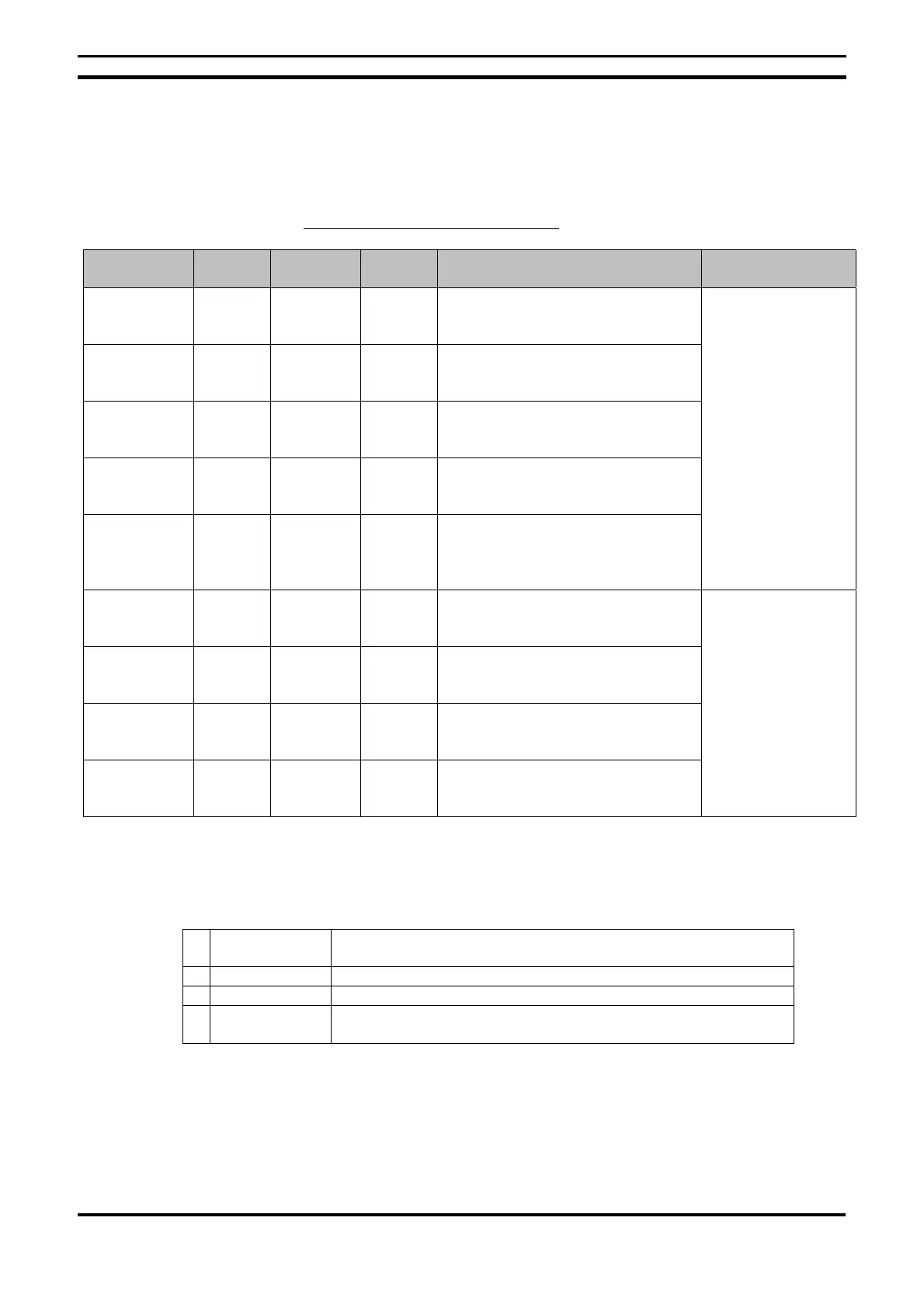
I/O, Work and Internal Holding Bits
Area name Symbol Bit
addresses
N° bits Function Ladder Program
Input bits I I0 to I5 6 Displays the ON/OFF status of the
input device connected to the CPU
input terminal
Expansion
input bits
X X0 to Xb 12 Displays the ON/OFF status of the
input device connected to the I/O
expansion unit input terminal
Button switch B B0 to B7 8 Displays the ON/OFF status of the
CPU operating switches (LCD-type
CPU)
Analog
comparator
A A0 to A3 4 Outputs the comparison result for
analog inputs. Only available for
models with a 24 Vcc power supply.
Comparator
bits
P P0 to Pf 16 Compares the present value of
timers (T), holding timers (#) and
counters (C) and outputs the
comparison result.
N.O. / N.C inputs
(see note 1)
Output bits Q Q0 to Q3 4 Displays the ON/OFF status of the
output deivces connected to the
CPU unit
Expansion
output bits
Y Y0 to Yf 16 Displays the ON/OFF status of the
output deivces connected to the I/O
expansion unit
Work relays M M0 to Mf 16 Can only be used with the ladder
program. Cannot output to an
external device.
Holding relays H H0 to Hf 16 The same as previous area but also
maintains its status even without
power supply on.
N.O. / N.C outputs
(see note 1.2)
Note
1 N.O. : Normally open N.C. : Normally closed
2 The following functions can be selected for output bits
[ Normal output Turns to ON or OFF according to the ON/OFF status of execution
condition
S Set When the condition is ON, the output turns to ON
R Reset When the condition is OFF, the output turns to OFF
A Alternative Alternates the output ON/OFFwhen the execution condition is in
ON

 Loading...


