5 I/O Addressing ZEN Programmable Logic Module
OMRON ELECTRONICS, S.A. Page 15
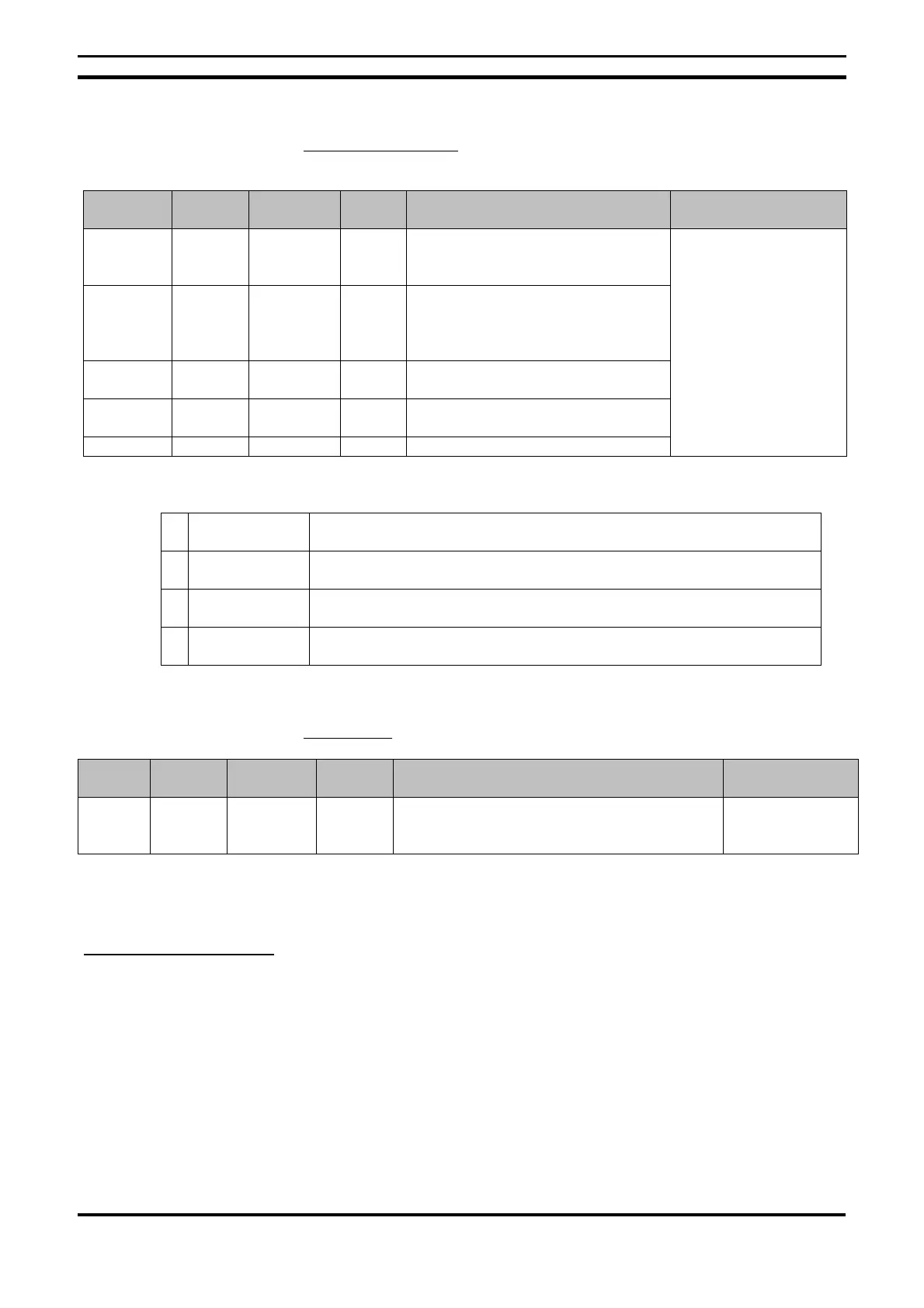
Timers and Counters
Area name Symbol Bit
addresses
N° bits Function Ladder Program
Timer T T0 to T7 8 Can be activated between ON-delay,
OFF-delay, one-shot and flashing
pulse operation.
Holding
timer
# #0 to #3 4 Maintains the timer value when the
trigger input is in OFF mode. The
timer will continue even if turned to
ON mode again.
Clock
timer
@ @0 to @7 8 Can be put into ON or OFF mode on
a specified day or period.
Calendar
timer
* *0 to *7 8 Can be put into ON or OFF mode on
a specified date.
Counter C C0 to C7 8 Reversible counter
N.O. / N. C condition
(see note 1)
Note Timers can have the following functions.
X ON delay Time elapsed from the moment the input is triggered until the set timer bit
turns to ON mode.
n OFF delay The timer bit turns to ON mode from the moment the input is triggered
until the set time has elapsed on the timer.
O One-shot The set timer bit turns the selected time to ON mode when the trigger
input switches from OFF to ON mode.
F Flashing pulse The set timer bit constantly switches from OFF to ON mode while the
trigger input remains in ON mode
Display Bits
Area
name
Symbol Bit
addresses
N° bits Function Ladder Program
Display D D0 to D7 8 Displays predefined messages relating to
timers, counters and their present values or
converted analog values.
Output
I/O Bit Addressing
The bit input addresses 10 to 15 and the bit output addresses Q0 to Q3 are
always allocated to the CPU unit.
Up to 3 I/O expansion units can be added, allocating these I/O points to the X0
to Xb input bits and Y0 to Yb as output bits, remembering the order of the
connected expansion units.

 Loading...


