7 Programming Functions ZEN Programmable Logic Module
OMRON ELECTRONICS, S.A. Page 22
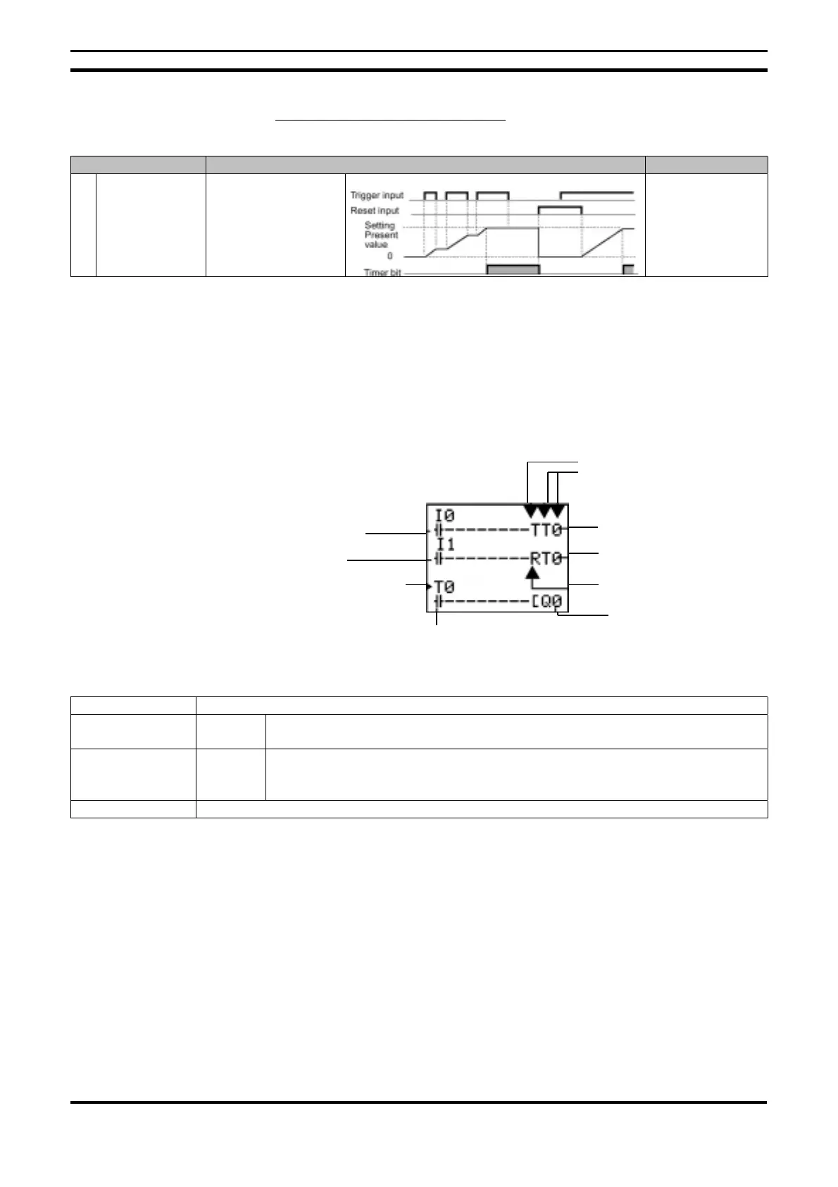
Holding Timer Operation (#0 to #3)
Timer Type Operation Applications
X Delay timer at
connection
Output is activated
when the set time
elapses as input is
triggered.
In systems where
timing must
continue even in
cases where
power suply is
null.
7.1.1. Settings in the Ladder Program
Input triggers, output resets and input timers are drawn on the ‘Edit Screen’.
The timer setting is carried out on the Parameter Settings Screen.
Timer address Timer: T0 to T7 Holding Timer : #0 to #3
Trigger input T (TRG) Controls the timer trigger output. Triggers the time when the trigger input
switches to ON mode.
Reset input R (RES) Controls the timer reset output. When the reset input switches to ON mode,
the present value is reset and the timer bit switches to OFF mode. The trigger
inputs are not active while the reset input is in ON mode.
Timer bit Turns ON mode according to the setting
Trigger specifications
Timer No.
Reset specifications
Time up output
Timer reset output
Timer trigger outputTrigger input
Reset input
Timer address
Timer bit

 Loading...


