7 Programming Functions ZEN Programmable Logic Module
OMRON ELECTRONICS, S.A. Page 25
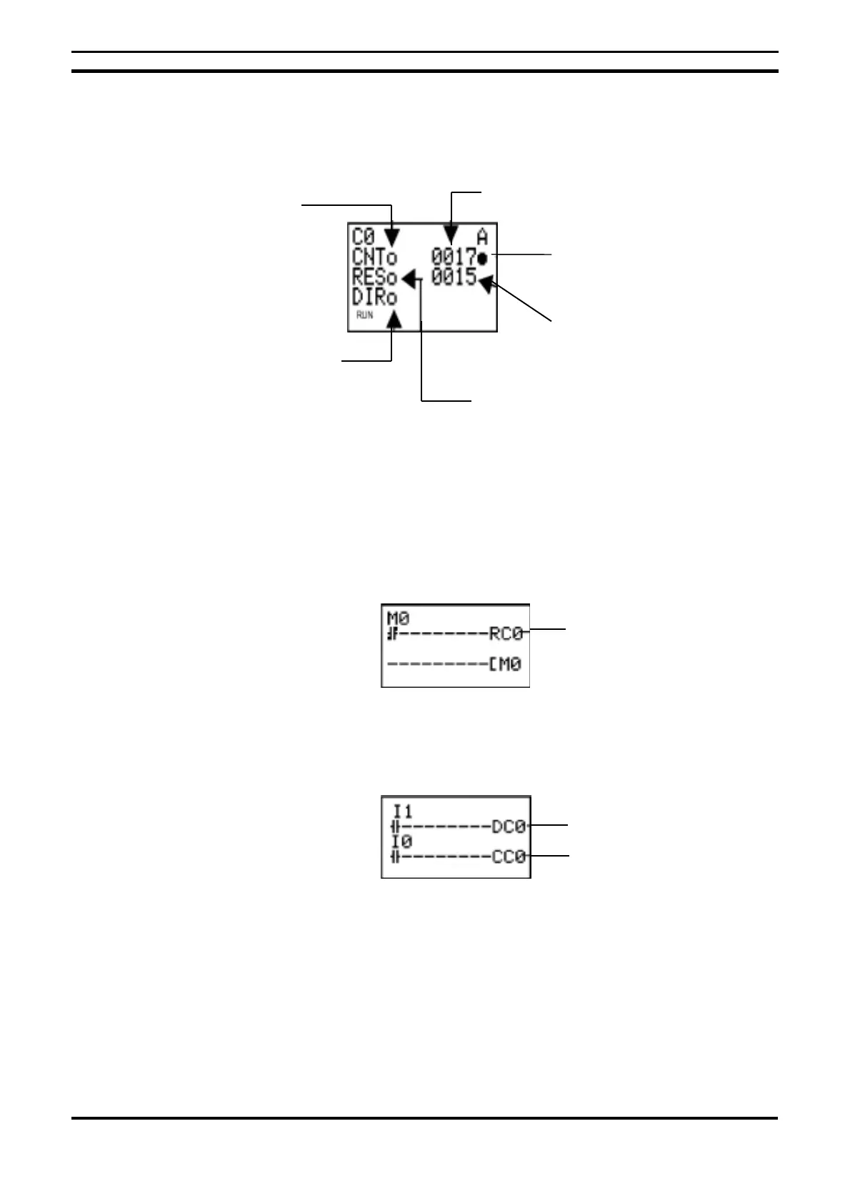
7.2.3. Parameter Monitoring on the Screen Display
Note.
1. To reset the present value and the counter bit status (ON/OFF mode) due
to a power supply fault or a change in operating mode, a reset circuit must
be created which should be activated first. This circuit may be something
like the following:
2. If the counter input and the counter direction are input simultaneously,
place the counter direction output in the program before the counter input.
7.3. Using Weekly Timers
Weekly timers switch to ON mode between the start time and the end of the
specified day. Weekly timers have 8 points (@0 to @7).
Counter reset output
Counter direction output
specification
Output to counter input
Counter present
Counter bit status
(l:ON/m:OFF)
Counter input status
(m:OFF/l:ON)
Counter No. input status
specification (m:OFF/l:ON)
Reset input status
(m:OFF/l:ON)
Instruction (set

 Loading...


