REMOTE CONTROL CONNECTIONS
Provision
is
made foraddition
of
remote starting. This
is accomplished
on a 4
place terminal block situated
within
the
control
box.
Connect
one
or
more remote
switches across remote terminal
and B+
terminal
as
shown
in
Figure
10. If
the
distance between
the
set
and remote station
is
less than 1000-feet,
use No.
18
AWG wire; between
1000-
and
2000-feet,
use No.
16AWG wire.
COMMON
ALARM
I
I
ALM
GRD RMT
REMOTE
SWITCH
B+
o
o
FIGURE
10.
REMOTE STARTING
WIRING CONNECTIONS
Most local regulations require that wiring connec-
tions
be
made
by a
licensed electrician
and
that
the
installation
be
inspected
and
approved before opera-
tion.
All
connections, wire sizes, etc. must conform
to
requirements
of
electrical codes
in
effect
at the
installation site.
If
the
installation
is for
standby service,
a
double
throw transfer switch must always
be
used. Connect
this switch (either automatic
or
manual)
so
that
it is
impossible
for
commercial power
and
generator
current
to
be
connected-to
the
load
at
the same time.
Instructions
for
connecting
an .
automatic load
transfer control
are
included with such equipment.
GEN.
LINE
LOAD
NOTE:
SHOWN WITH LINE CONNECTED
TO
LOAD.
FIGURE
11.
LOAD TRANSFER SWITCH
Control
Box
Connections: The factory ships these
12
lead generators with load connection wires
NOT
connected together
in
the control box. These 12 wires
are labeled
Tl
through
T12 and
must
be
brought
together before making load connections. Proceed
as
follows:
1.
Remove either right, left
or top
panel from control
box.
See
Figure
12.
2.
Connect wires together as shown
on
panel and
in
Figure
13
according
to
voltage desired.
3. Open hinged control panel doors. Connect lead
from terminal
63 to
correct terminal
for
voltage
desired.
These terminals
are
labeled
H2, H3, H4,
H5
and H6. See
Figure
14.
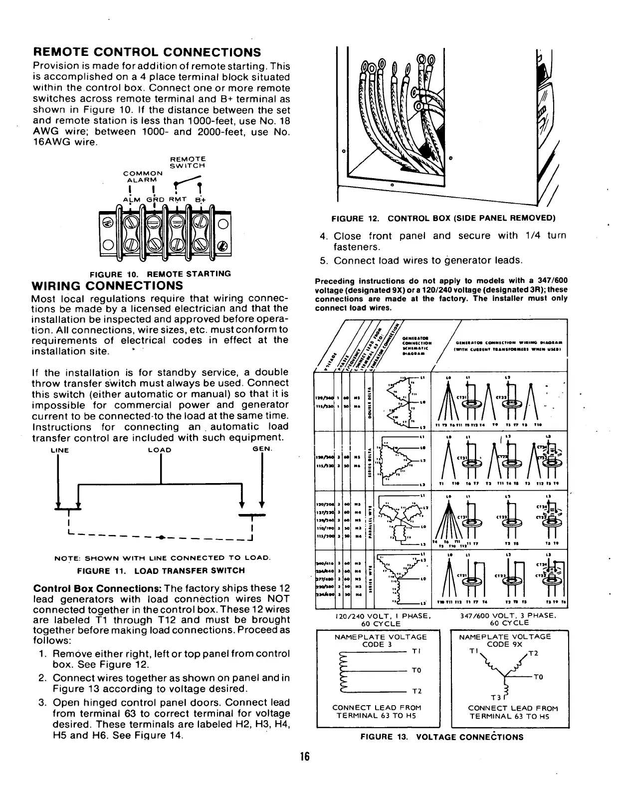
FIGURE
12.
CONTROL
BOX
(SIDE PANEL REMOVED)
4.
Close front panel
and
secure with
1/4
turn
fasteners.
5. Connect load wires
to
generator leads.
Preceding instructions
do not
apply
to
models with
a
347/600
voltage (designated 9X)
or
a
120/240 voltage (designated 3R); Ihese
connections
are
made
at the
factory.
The
installer must only
connect load wires.
MNIIATM
COMNICIIOM
tCNIMATIC
•1AOIAM
OIMIIATM COMNICTIOM WltlMG •lAOBAM
(WITH CUIIINf TIANftMMMiaS
WMM
UMBI
IM/MO
m/uo
iar/*io
US/IO0
i»«A«o
in/400
ntfuo
IMAOO
ii
n
?»tn
nm
T4
l«
TITT
1> IIO
TI
no i*
17
ta in
14
to ia in ii io
IW til
111
11 TT
14
11
11
11
120/240 VOLT,
I
PHASE,
60 CYCLE
347/600 VOLT.
3
PHASE,
60 CYCLE
NAMEPLATE VOLTAGE
CODE
3
Tl
TO
T2
CONNECT
LEAD
FROM
TERMINAL
63
TO H5
NAMEPLATE VOLTAGE
CODE
9X
Tl
*
,T2
•TO
T3
CONNECT LEAD FROM
TERMINAL
63 TO H5
FIGURE
13.
VOLTAGE CONNECTIONS
16
 Loading...


