MANTA USER’S MANUAL
22
07
RepaiRs and Replacements
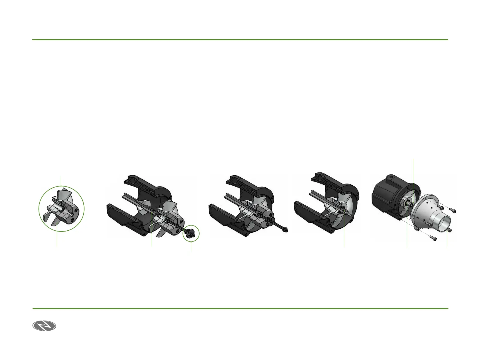
1. Hold the tool (7) next
to the impeller (A)and
screw the 3 socket head
screws (2) using the hex
key SW2,5 . The tool and
impeller will be fixed
to one another as you
may see in the picture
below. “assembly 1”.
2. Manually introduce the
assembly 1 to the Jet Unit
through the shaft (B) as
far as possible without
applying excessive force
3. Screw knurled nut (3) to
the threaded rod (1) with
the hexagon domed cap
(8) and introduce the flat
washer (4) creating the
“assembly 2”.
4. Pass the assembly 2
through the tool’s (7) hole
and screw the threaded
rod (1) to the JetUnit’s
shaft (B) holding it from
the hex cap (8).
5.
Hold the tool (7) while
turning the knurled nut (3)
clockwise. The assembly 1
& 2 while slightly mount on
the the Jetpack’s Shaft (B).
6.
Once the Impeller reaches the
end of its trajectory, unscrew
the assembly 2 from the
shaft (B) holding it from the
hexagonal cap (8).
7. Unscrew the tool from the
impeller.
8. Mount a new Circlip
(Seeger ring).
9. In order to mount the
Stator/Nozzle assembly
back to the Jet Unit, it is
recommended to apply
grease on the Jet Unit’s
shaft. Push the assembly
Stator/Nozzle onto the
shaft and screw the 5
socket head screws using
the hex key SW3.
DESIGNED
CHECKED
Group :
UNLESS OTHERWISE SPECIFIED
DIMENSIONS ARE IN MILLIMETERS
NAME
disen
DATE
10/05/16
TITLE
SIZE
A1
DWG NO REV
FILE NAME: WaterPump_montaje Impeller.dft
SCALE:
WEIGHT:
SHEET 2 OF 4
REVISION HISTORY
DESCRIPTION
REV
DATE
NAME
The content of this drawing and the intellectual property are property of Aquila Boards S.L.U ( Avda. de la Ribera de Axpe nº11B Mod 210, 48950 Erandio, Bizkaia, Spain), and can't be reproduced or used without their explicit written consent
General Tolerances : Deviation of dimensions without
tolerance according to DIN ISO 2768 -mK
MATERIAL :
A
INITIAL DRAWING CREATION 10/05/16
disen
Surface Finish
0,000 kg
Onean
1:1
WaterPump.asm
Assembling a new impeller to the water
pump:
II) Introduce manually the assembly (I) into the shaft (B) as far as possible without applying too
much force.
Screw the knurled knob (5) to the threaded rod with cap (2) and mount the washer (6) building
the assembly (II).
Introduce the assembly (II) through the assembly (I) and screw the assembly (II) to the pump´s
shaft (B).
III) Turn the knurled knob (5) while holding the tool (1) with the
hands until the end.
IV) Detach the mounting tool by unscrewing the knurled knob,
screws and threaded rod. Mount the circlip (C).
I) Hold the tool (1) next to the impeller (A) and screw the three screws (3)
until the end with the allen key SW2,5 provided in the tooling box, building
the assembly (I)
I) Unmount the Circlip (C) and screw the hexagonal head screw (7)
into the pump shaft (A).
II) Hold the tool (1) next to the impeller while screwing the three
screws (3) until the end with the allen key SW2,5 provided in the
tooling box.
Manually screw the socket set screw (8) to the impeller tool until
the end (until it touches the hexagonal screw (3).
III) Screw the socket set screw while holding the tool (1) with the
SW3 wrench provided in the tool box.
Detaching the impeller from the water pump:
Assembling the nozzle to the jet:
If available, apply some grease to the shaft´s top at first.
Push the Stator-Nozzle assembly into the Pumps shaft (B) and screw the five
screws DIN 912 m4x12 to the Jet´s housing.
Disassembling the nozzle from the jet:
Unscrew the five screws DIN 912 m4x12 to the Jet´s housing, hold the nozzle and
pull manualy the assembly out of its shaft.
Item
Number
File Name (no extension) Quantity Material
1 din_976_m4x65_A2 1 Stainless Steel
2 din_en_iso_4762_m3x30 3 Stainless Steel
3 din_466_m4_0_5 1 Stainless Steel
4 din125-1-a_4_3-140_hv 1 Stainless Steel
5 screw_din_933-m4x6-10_9
-a
1 Stainless Steel
6 din_913-m6x50-45h 1 Stainless Steel
7 unmount_tool_s 1 Anodized tempered Aluminum
8 din1587-m4x0_76 1 Stainless Steel
ToolBox
SW 13-14 T-wrench
1x Allen key SW3
1x Allen key SW2,5
DESIGNED
CHECKED
Group :
UNLESS OTHERWISE SPECIFIED
DIMENSIONS ARE IN MILLIMETERS
NAME
disen
DATE
10/05/16
TITLE
SIZE
A1
DWG NO REV
FILE NAME: WaterPump_montaje Impeller.dft
SCALE:
WEIGHT:
SHEET 2 OF 4
REVISION HISTORY
DESCRIPTION
REV
DATE
NAME
The content of this drawing and the intellectual property are property of Aquila Boards S.L.U ( Avda. de la Ribera de Axpe nº11B Mod 210, 48950 Erandio, Bizkaia, Spain), and can't be reproduced or used wit hout their explicit written consent
General Tolerances : Deviation of dimensions without
tolerance according to DIN ISO 2768 -mK
MATERIAL :
A
INITIAL DRAWING CREATION 10/05/16
disen
Surface Finish
0,000 kg
Onean
1:1
WaterPump.asm
Assembling a new impeller to the water
pump:
II) Introduce manually the assembly (I) into the shaft (B) as far as possible without applying too
much force.
Screw the knurled knob (5) to the threaded rod with cap (2) and mount the washer (6) building
the assembly (II).
Introduce the assembly (II) through the assembly (I) and screw the assembly (II) to the pump´s
shaft (B).
III) Turn the knurled knob (5) while holding the tool (1) with the
hands until the end.
IV) Detach the mounting tool by unscrewing the knurled knob,
screws and threaded rod. Mount the circlip (C).
I) Hold the tool (1) next to the impeller (A) and screw the three screws (3)
until the end with the allen key SW2,5 provided in the tooling box, building
the assembly (I)
I) Unmount the Circlip (C) and screw the hexagonal head screw (7)
into the pump shaft (A).
II) Hold the tool (1) next to the impeller while screwing the three
screws (3) until the end with the allen key SW2,5 provided in the
tooling box.
Manually screw the socket set screw (8) to the impeller tool until
the end (until it touches the hexagonal screw (3).
III) Screw the socket set screw while holding the tool (1) with the
SW3 wrench provided in the tool box.
Detaching the impeller from the water pump:
Assembling the nozzle to the jet:
If available, apply some grease to the shaft´s top at first.
Push the Stator-Nozzle assembly into the Pumps shaft (B) and screw the five
screws DIN 912 m4x12 to the Jet´s housing.
Disassembling the nozzle from the jet:
Unscrew the five screws DIN 912 m4x12 to the Jet´s housing, hold the nozzle and
pull manualy the assembly out of its shaft.
Item
Number
File Name (no extension) Quantity Material
1 din_976_m4x65_A2 1 Stainless Steel
2 din_en_iso_4762_m3x30 3 Stainless Steel
3 din_466_m4_0_5 1 Stainless Steel
4 din125-1-a_4_3-140_hv 1 Stainless Steel
5 screw_din_933-m4x6-10_9
-a
1 Stainless Steel
6 din_913-m6x50-45h 1 Stainless Steel
7 unmount_tool_s 1 Anodized tempered Aluminum
8 din1587-m4x0_76 1 Stainless Steel
ToolBox
SW 13-14 T-wrench
1x Allen key SW3
1x Allen key SW2,5
7.1.2. Mounting the iMPeLLer
A B B B
Apply grease
D
assembly 2
assembly 1