14 Oneida Air Systems
Assembly Instructions (Continued)
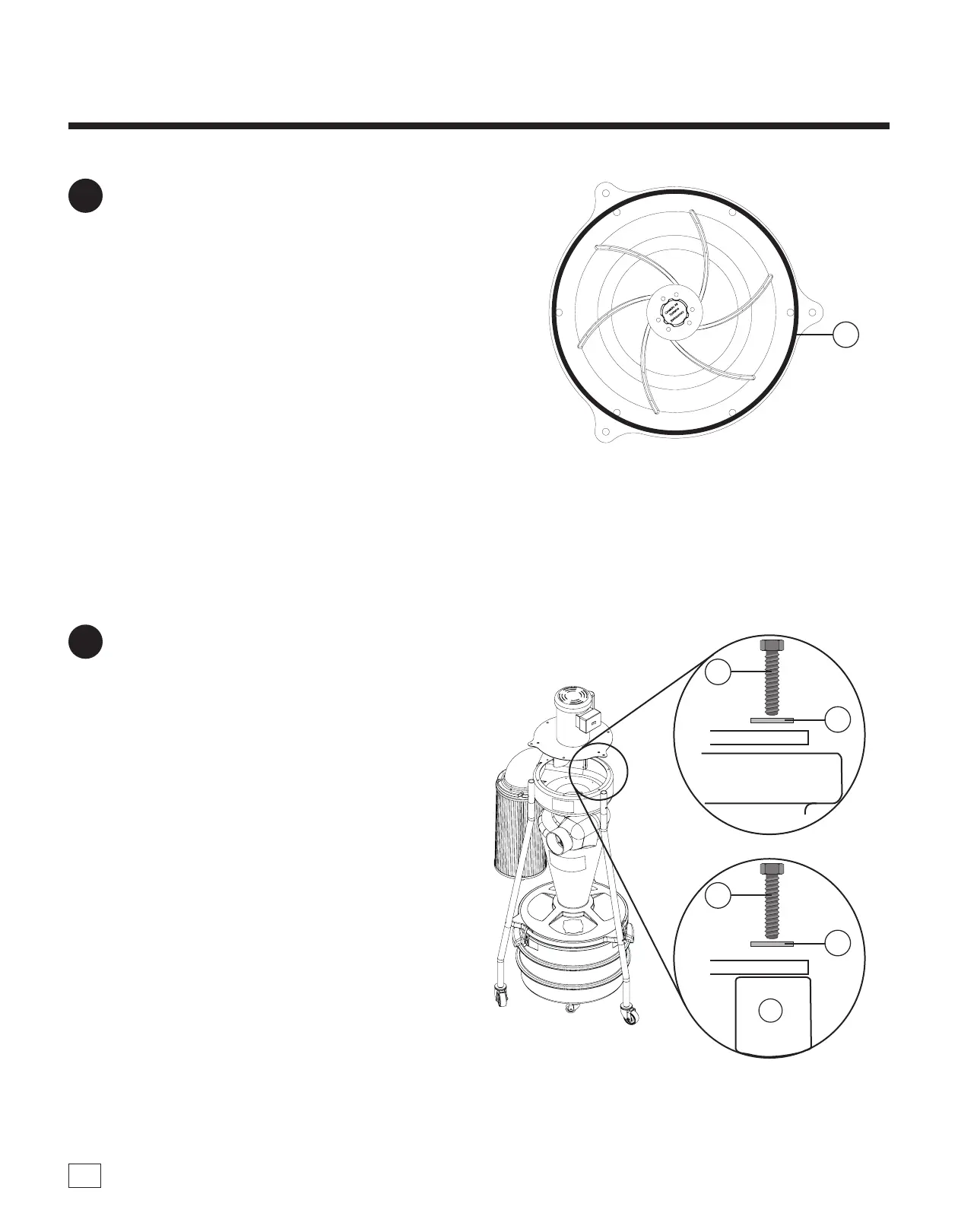
FIG. 9
Carefully li the Motor Assembly (A) on top of
the unit and align the motor plate holes with the
fan housing holes and the threaded inserts on
top of the legs [FIG. 10]. read and tighten the
nine 5/16" x 1" Hex Head Bolts (C9S) and nine
5/16" Flat Washers (C9T).
Tighten all of the hardware; this includes the
pre-installed parts used on the Drum Latches
(C2) and the Drum Window (C6)
Note: If U-Spring Nuts (C9R) don't align with
the motor plate holes, use a screwdriver to adjust
misalignment. Hand tighten rst and then tighten
down.
10
The motor assembly is very heavy and cumbersome; Be sure to have adequate help to lift the
motor assembly up!
Apply the Gasket (C9C) to the motor plate as
shown in [FIG 9], making sure that there is no
gap where the ends meet.
Note: Dust collection systems cannot operate
eectively if there isn’t a complete seal. ere must
be NO air leaks.
9
Motor Plate
PLACE GASKET AROUND OUTER PERIMETER
OF MOTOR PLATE.
C9S
C9T
Fan Housing
Motor Plate
C9S
C9T
FIG. 10
C8
C9C
 Loading...