16 Oneida Air Systems
Assembly Instructions (Continued)
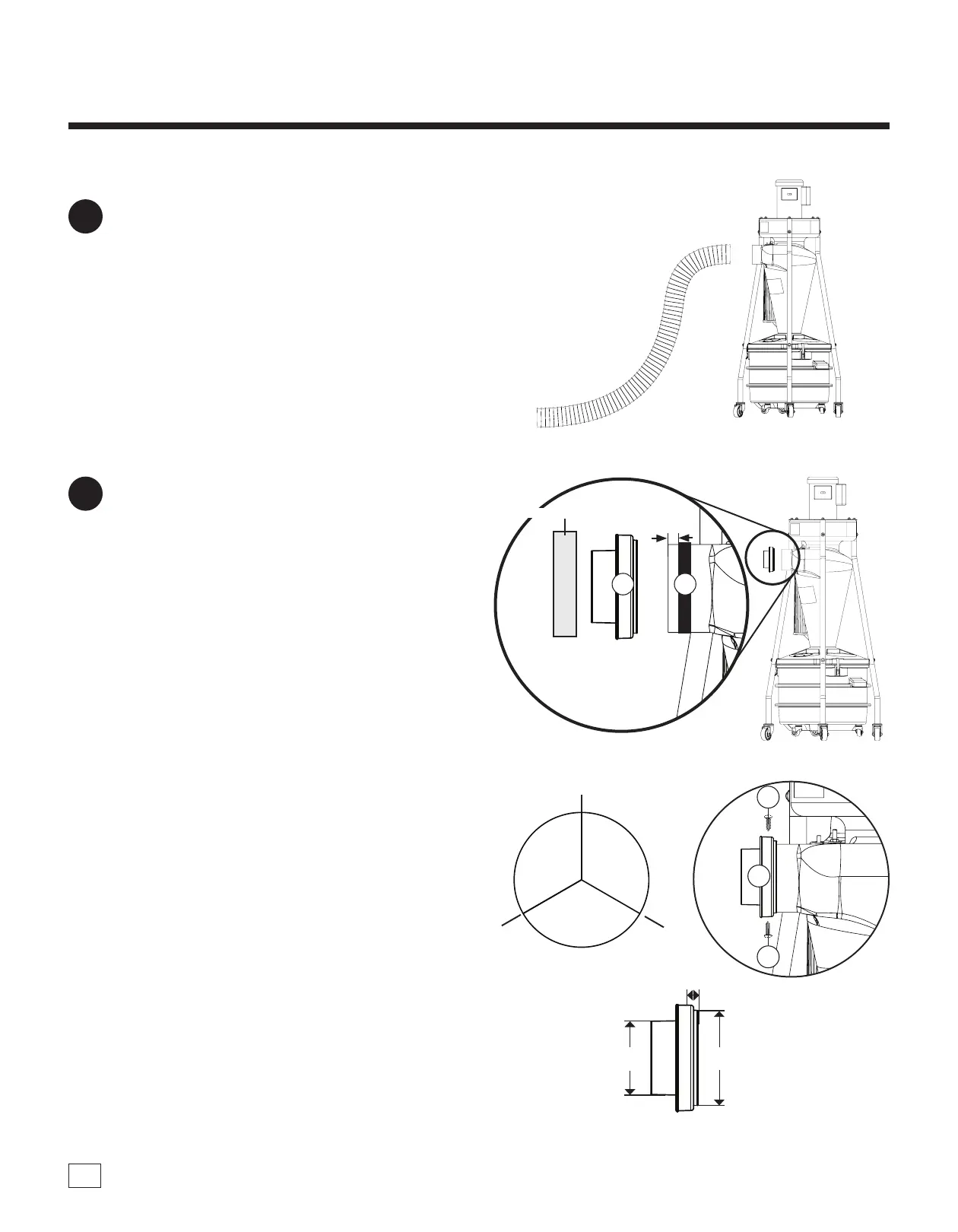
If you plan to hook ve inch ex hose to the
inlet, it will be a snug t. Pull ends up little
by little to work the hose onto the cyclone’s
discharge [FIG. 13].
Note: Pliers can be used to grab the reinforcing
wire and aid in pulling the hose over the opening.
13
1/4"
6 mm
1/2"
13 mm
5"
127 mm
4"
102 mm
FIG. 13
FIG. 14b
FIG. 14a
FIG. 14c
FIG. 14d
D2
D3
D3
D1
D1
Wooden Block
Pre-Drill
Pre-Drill
Pre-Drill
120°
120°
120°
If you plan to hook four inch ex hose to the
inlet , slide the 1/2" Silicone Band (D2) around
the cyclone’s 5" inlet so that it is 1/4" from the
edge. Push the 4" Reducer Adapter (D1) rmly
onto the inlet and over Silicone Band. Use a
wooden block and mallet to gently seat the
adapter into place (using the wooden block to
evenly distribute the force and avoid deforming
the molded adapter) [FIG. 14a].
For a more secure t, the included Screws
(D3) can be used to permanently attach the 4"
Reducer Adapter. Prior to installing the Adapter,
mark three locations around the outside edge at
120-degree increments [FIG. 14b] and 1/2" from
the edge [FIG. 14c]. Pre-drill three 1/8" diameter
holes at these locations. en install three #8 x
1/2" Screws into these holes aer installing the
Adapter [FIG. 14d].
14
 Loading...