1500 North Belcher Road, Clearwater, FL 33765 • Tel (727) 447-6140 • Fax (727) 442-5699 • sales@onicon.com
Turbine Flow Meter Manual 05/13 - 0721-1 / 13518 Page 38
8-20-010275
1500 North Belcher Road, Clearwater, Florida 33765 Tel (727) 447-6140 Fax (727) 442-5699
www.onicon.com E-mail: sales@onicon.com
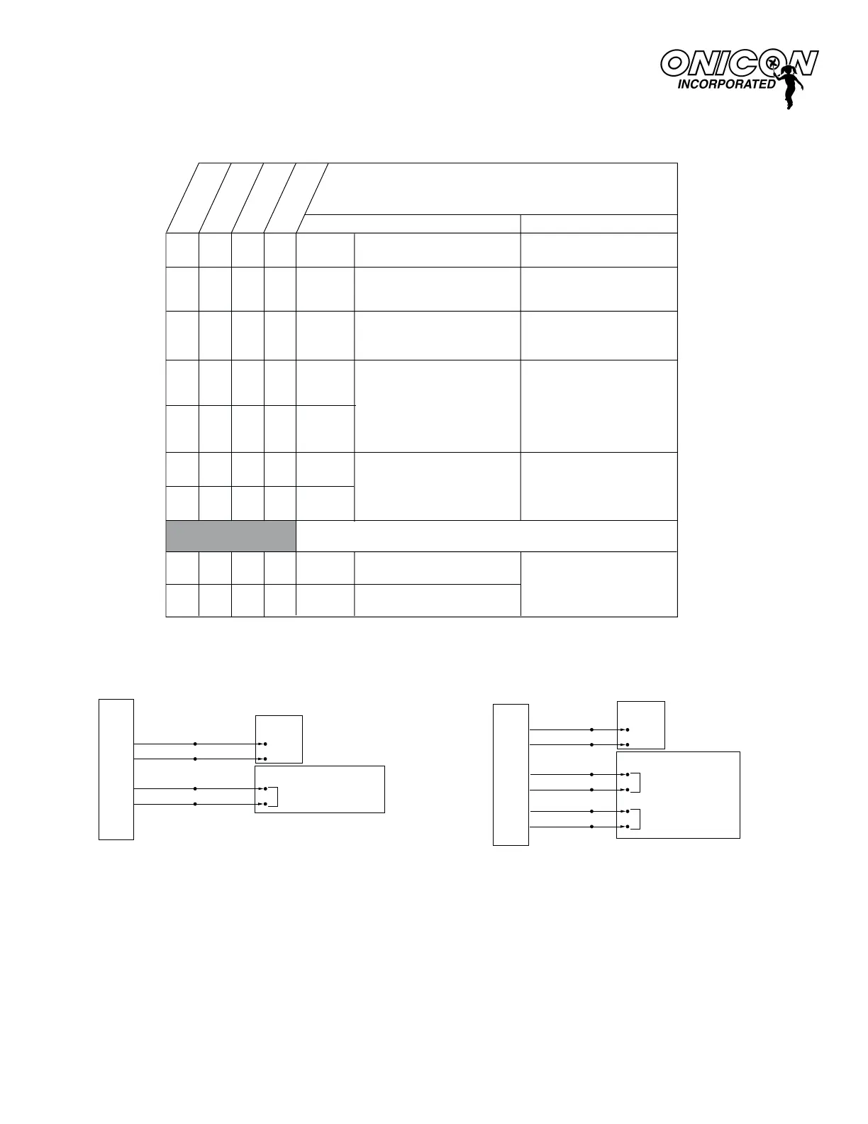
FLOW METER WIRING INFORMATION
User Connections for Models with Scaled Output
Models: F-1130, F-1230, FB-1230 & F-1330
Wiring Information
WIRE COLOR CODE NOTES
(+) 24 ± 4 V AC/DC
supply voltage
RED
*
BLACK
(–) Common ground
(Common with pipe ground)
Connect to power supply
negative
GREEN
(+) Frequency output signal:
0-15 V peak pulse
Required when meter
is connected to local
display or BTU meter
BLUE
Dry contact scaled
output
Scaled to provide one
pulse per volumetric unit
Examples:
1 pulse per 10 gal.
1 pulse per 100 gal.
BROWN
GRAY
VIOLET
Dry contact directional
output - indicates
flow direction
Contact closed when flow
is in direction of arrow
on meter
DIAGNOSTIC SIGNALS
ORANGE
Bottom turbine frequency
WHITE
Top turbine frequency
These signals are for
diagnostic purposes -
connect to local display
or BTU meter
Connect to power supply
positive
√
√
√
√
√
√
√
√
√
√
√
√
√
√
√
√
√
√
√
√
√
√
√
√
√
√
F-1130
Single Turbine
F-1330
Inline
F-1230
Dual Turbine
FB-1230
Bi-Directional
FB-1230 Wiring Diagram
Connections to a Control System (No Display or BTU Meter)
F-1130 / F-1230 / F-1330 Wiring Diagram
Connections to a Control System (No Display or BTU Meter)
NOTES:
*
1. Serial Numbers 115691 and earlier require 24 VDC. Serial Numbers 115692 and higher
can accept 24 V AC/DC.
2. Black wire is common with the pipe (typically earth ground).
3. For ONICON display module or BTU meter, connect all wires provided. Refer to wiring diagram
provided with display or BTU meter.
4. This is NOT a "loop-powered" instrument. DO NOT connect power to any of the signal
output wires (blue, brown, green, orange or white)
FLOW METER
FLOW METER
RED
BLACK
BLUE
BROWN
GRAY
VIOLET
Power
Source
+ 24 V
COM
Control System
BINARY (DIGITAL) INPUT
(Rate)
BINARY (DIGITAL) INPUT
(Direction)
RED
BLACK
BLUE
BROWN
+ 24 V
COM
Power
Source
Control System
BINARY (DIGITAL) INPUT
0275 08-01
 Loading...


