Standard I/O
4 -20mA Flow or Temperature
Pulse or Alarm
USB
(Free F-5000 View Software)
Outputs and Communications are
Galvanically Isolated
Selectable Output Options
RS485 Modbus RTU, BACnet MS/TP
HART Communication
Standard Digital Communications
12-28VDC Input Power
Display and
Conguration Panel
F1
F2 F3 F4
FLOW
AND
ENERGY
MEASUREMENT
F-5500 Functional Diagram
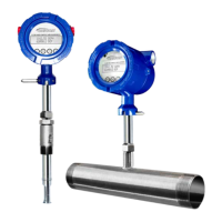
An on-board 2 line x 16 character backlit LCD display shows flow rate, total flow,
elapsed time, process gas temperature, and alarms. The display is also used in
conjunction with the User Interface for field configuration of flow meter settings such
as 4-20mA scaling, frequency output scaling, pipe area, zero flow cutoff, flow filtering
or dampening, display configurations, diagnostics, and alarm limits.
Fig. 1.8: F-5500 Function Diagram
11451 Belcher Road South, Largo, FL 33773 • USA • Tel +1 (727) 447-6140 • Fax +1 (727) 442-5699 • sales@onicon.com
F-5500 Thermal Mass Flow Meter Manual 06/17 - 2030 / 107023 Page 14
Model F-5500
DISCLAIMERINTRODUCTION
Display
Introduction
 Loading...