i
Fig. 3.8-3.9, IMPORTANT NOTES:
• When using a 12 volt power supply, the load resistor on the 4-20mA output must be
125 ohms or less to operate properly.
• When using 24 volt power, the load resistor is typically 250 ohms. A 250 ohm
resistor in the 4-20mA circuit will result in a 1 to 5 volt signal to the PLC or DCS.
• When using a 24 volt power supply, the load resistor on the 4-20mA output must be
600 ohms or less.
• Some PLC and DCS equipment have built in load resistors, please refer to the
technical manuals of such equipment.
11451 Belcher Road South, Largo, FL 33773 • USA • Tel +1 (727) 447-6140 • Fax +1 (727) 442-5699 • sales@onicon.com
F-5500 Thermal Mass Flow Meter Manual 06/17 - 2030 / 107023 Page 36
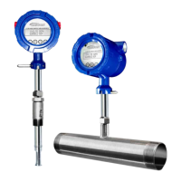
Model F-5500
WIRING
Wiring: HART
HART Wiring
i
Fig. 3.7, IMPORTANT NOTE:
The load resistor on the ONICON Flow Meter 4-20mA signal is typically 250 ohms
and is located in or at the customer's PLC or DCS. A 250 ohm resistor in the 4-20mA
line will result in a 1 to 5VDC signal to the PLC or DCS. Some PLC/DCS equipment
has the load resistor built in to the unit; please refer to the PLC/DCS technical manual.
Do not exceed a 600 ohm load on the ONICON Flow Meter 4-20mA signal.
(
-
) (+) (
-
) (+) (
-
) (+)
Power
12-28VDC
4-20mA Pulse
/Alarm
!
+12 to 28VDC
12 to 28VDC Return
*(see important note below)
F-5500
Customer PLC or DCS
HART
Modem
HART Wiring
The HART connections are accessed by removing the cover of the F-5500 enclosure.
HART 4-20mA Output Wiring: Customer-Supplied Power Source
The 4-20mA current loop and HART modem connections are made as shown in the
diagram below.
Fig. 3.7: HART Wiring
, Customer-Supplied Power Source