Installation -
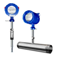
Model F-5500
Flow Meter
Scope
This section describes how to install the ONICON Model F-5500 Flow Meter and how
to get started:
1. Determine lateral position on the pipe
2. Sensor installation depth
3. Sensor orientation in relation to sensor length and direction of flow
4. Proper tightening of compression fitting for mounting meter
Installation procedures must be performed using a combination of the end user’s
best engineering practices, in compliance with local codes, and manufacturer’s
recommendations.
General Precautions
The following general precautions should be observed:
1. Exercise care when handling the flow meter to avoid damaging the probe, sensor
or enclosure.
2. The enclosure cover must be closed except during installation or configuration.
3. Mounting F-5500 in direct sunlight can cause the temperature inside the enclosure
to increase beyond design limits, resulting in failure of LCD display and reduced
component life. It is recommended that a sunshade be installed to avoid direct
sunlight (see maximum enclosure operating temperature specification in appendix).
4. Ensure the flow direction indicator/pointer for the meter is in line with the direction
of flow in the pipe.
5. Do not install the F-5500 enclosure near an igniter, igniter-controller or switching
equipment.
6. Do not install an external power supply in a cabinet containing an igniter controller
or switching equipment.
7. For accurate flow measurement: review flow meter placement instructions before
installation to ensure a proper flow profile in the pipe.
11451 Belcher Road South, Largo, FL 33773 • USA • Tel +1 (727) 447-6140 • Fax +1 (727) 442-5699 • sales@onicon.com
F-5500 Thermal Mass Flow Meter Manual 06/17 - 2030 / 107023 Page 17
Model F-5500
INTRODUCTION
Installation: General