FLOW
Downstream
Proper
Flow
Prole
Upstream
Irregular Flow
Prole
Flow Direction
Indicator
F1
F2 F3 F4
F1
F2 F3 F4
Do not substitute threaded tees for
the welded branch outlet. Contact
ONICON if you need installation
hardware for threaded pipe.
i
i
Instructions for Insertion Flow Meter Lateral Placement
Install the Model F-5500 Insertion style flow meter so that it is far enough away from
bends in the pipe, obstructions, or changes in line sizes to ensure a consistent flow
profile. Review straight run requirements table on p. 21.
NOTE: The probe diameter is ¾".
Fig. 2.1: Upstream and Downstream Pipe IDs for Insertion Meters
Special Conditions of Use:
• Consult the manufacturer if dimensional information on the flameproof
joints is necessary.
• The flamepaths of the equipment are not intended to be repaired. Consult
the manufacturer if repair of the flamepath joints is necessary
• Follow the manufacturer's instructions to reduce the potential of an
electrostatic charging hazard.
NOTE: An irregular flow profile may affect sensor accuracy.
11451 Belcher Road South, Largo, FL 33773 • USA • Tel +1 (727) 447-6140 • Fax +1 (727) 442-5699 • sales@onicon.com
F-5500 Thermal Mass Flow Meter Manual 06/17 - 2030 / 107023 Page 18
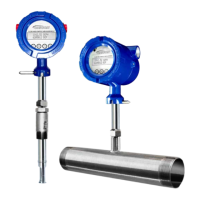
Model F-5500
INSTALLATION
Installation: Insertion Type
Insertion Flow
Meter Lateral
Placement
Installation
Hardware
 Loading...