FLOW
Downstream
Proper
Prole
Upstream
Irregular
Prole
F1
F2 F3 F4
Flow Direction
Indicator
F1
F2 F3 F4
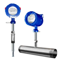
Model F-5500
INSTALLATION
11451 Belcher Road South, Largo, FL 33773 • USA • Tel +1 (727) 447-6140 • Fax +1 (727) 442-5699 • sales@onicon.com
F-5500 Thermal Mass Flow Meter Manual 06/17 - 2030 / 107023 Page 26
Instructions for Inline Flow Meter Placement
Install the Model F-5500 Inline style flow meter so that it is far enough away from
bends in the pipe, obstructions, or changes in line sizes to ensure a consistent flow
profile. Review the straight run requirements table on p. 27.
The Model F-5500 is threaded or flanged to the customer’s pipe. Care should be
taken to ensure that the diameter of the mating pipe is the same diameter as the Model
F-5500 flow body or errors in flow readings can occur. The installation procedure
should be a combination of the end user’s best engineering practices, in compliance
with local codes, and the manufacturer’s recommendations.
See "Fig. 2.11: Straight Run Requirements for Upstream Obstructions - Inline" on page
27 for a detailed look at upstream and downstream pipe diameters for inline meters.
Fig. 2.10: Upstream and Downstream Pipe IDs for Inline Meters
Flow Meter
Placement
Inline Type
Installation: Inline Type
Flow Body
Orientation
Inline Type
 Loading...