11451 Belcher Road South, Largo, FL 33773 • USA • Tel +1 (727) 447-6140 • Fax +1 (727) 442-5699 • sales@onicon.com
System-10-P1 Manual 09/15 - 0656-11 / 18320 A - 1 4
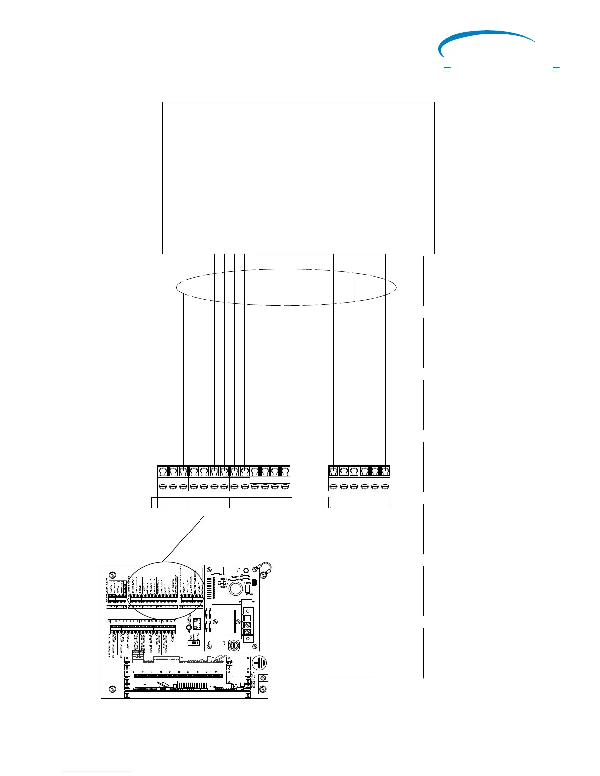
SYSTEM-10 BTU METER MOTHER BOARD
Inline Electromagnetic
Flow Meter Input Connections
J1
5
G
60HZ
1
J2-1
+15
+24
J2-12
G
G
10
R7
H3
R1
20075-50 REV. A
LED1
T1
D1
D2
VAR1
F1
1 AMP
TB1
D4
D3
H1
1
Analog Common -
* Frequency -
* Frequency +
4-20mA +
(B) Scaled +
(B) Scaled -
Flow Meter Inputs
* Shield
Auxiliary Flow Meter Signals
Earth
(A) Direction +
(A) Direction -
Terminal #
* (+) Pulse Output # 1
* (-) Pulse Output # 1
16
17
(+) Pulse Output # 2
(-) Pulse Output # 2
18
19
(+) 4-20mA Output
(-) 4-20mA Output
9
10
(+) Pulse Output # 2
(-) Pulse Output # 2
18
19
The System-10 does not provide power to the F-3100 or F-3200 flow mete
r. Input power for the flow
meter must be provided separatel
y
. See flow meter manual for detailed wiring instructions.
Connections shown with * are required for all models. Connections shown with (A) are required for bi-directional
flow installations. Connections shown with (B) are for unidirectional installations.
Inputs &
Outputs
T4
1
2
3
4
5
6
7
8
9
10
11
12
13
T5
1
2
3
4
5
6
F-3100 and F-3200 Flow Meter
Terminal Connections
L1 N Not Used
ON
I
CON
Flow and Energy Measurement
 Loading...


