11451 Belcher Road South, Largo, FL 33773 • USA • Tel +1 (727) 447-6140 • Fax +1 (727) 442-5699 • sales@onicon.com
System-10-P1 Manual 09/15 - 0656-11 / 18320 A - 1 5
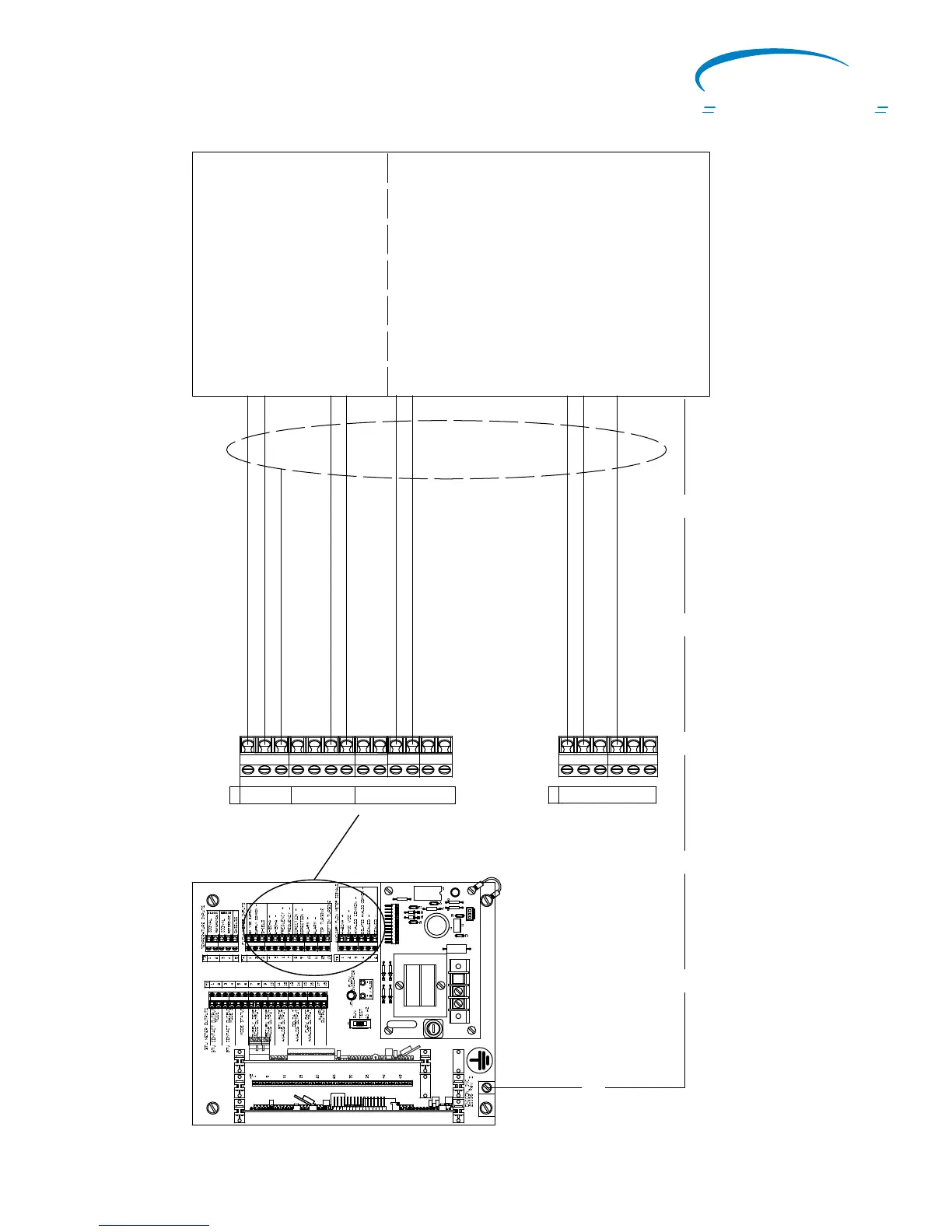
SYSTEM-10 BTU METER MOTHER BOARD
F-3500 Insertion Electromagnetic
Flow Meter Input Connections
J1
5
G
60HZ
1
J2-1
+15
+24
J2-12
G
G
10
R7
H3
R1
20075-50 REV. A
LED1
T1
D1
D2
VAR1
F1
1/8 AMP
TB1
D4
D3
H1
1
Connections shown for T5-1 and T5-2
are for the same analog output from the
F-3500. This output can be configured in
the flow meter as a 4-20mA or 0 -10 VDC.
0-10 VDC + (Blue)
* Frequency - (Yellow)
* 24VDC Supply + (Red)
* Supply Common - (Black)
* Frequency + (Green)
F-3500 Flow Meter Connections
Connections shown with * are required.
4-20mA + (Blue)
Flow Meter Inputs
* Shield
Auxiliary Flow Meter Signals
Isolated Analog Common - (Brown)
Earth (Green/Yellow)*
Factory Installed Cable
T4
1
2
3
4
5
6
7
8
9
10
11
12
13
T5
1
2
3
4
5
6
Alarm - (White)
Alarm + (Orange)
Connections shown below dashed line
are for flow meter output signals not used
by the BTU meter. Both incoming and
outgoing connections are made to the
same terminal.
L1 N Not Used
ON
I
CON
Flow and Energy Measurement
 Loading...


