EasyManua.ls Logo

Onkyo A-9155 User Manual

Onkyo A-9155
10 pages
To Next Page IconTo Next Page
Page #1 background imageLoading...
Page #1 background image
A-9155
SERVICE MANUAL
SERVICE MANUAL
RC-627S
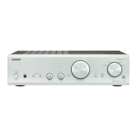
INTEGRATED AMPLIFIER
Black and Silver models
MODEL A-9155
230V AC, 50Hz
230V AC, 50Hz
B MPP
S MPP
Ref. No. 3991
042007
SAFETY-RELATED COMPONENT
WARNING!!
COMPONENTS IDENTIFIED BY MARK ON THE
SCHEMATIC DIAGRAM AND IN THE PARTS LIST ARE
CRITICAL FOR RISK OF FIRE AND ELECTRIC SHOCK.
REPLACE THESE COMPONENTS WITH ONKYO
PARTS WHOSE PART NUMBERS APPEAR AS SHOWN
IN THIS MANUAL.
MAKE LEAKAGE-CURRENT OR RESISTANCE
MEASUREMENTS TO DETERMINE THAT EXPOSED
PARTS ARE ACCEPTABLY INSULATED FROM THE
SUPPLY CIRCUIT BEFORE RETURNING THE
APPLIANCE TO THE CUSTOMER.
Question and Answer IconNeed help?

Do you have a question about the Onkyo A-9155 and is the answer not in the manual?

Onkyo A-9155 Specifications

General IconGeneral
Impedance4 Ω
Frequency range10 - 100000 Hz
Signal-to-Noise Ratio (SNR)100 dB
Total Harmonic Distortion (THD)0.08 %
Dimensions (WxDxH)435 x 121 x 344 mm
Power requirementsAC 220-230 V, 50/60 Hz
Output power description65 W/Ch
Product colorBlack
Power consumption (standby)0.2 W
Power consumption (typical)160 W
Weight and Dimensions IconWeight and Dimensions
Weight6800 g

Summary

SAFETY-RELATED COMPONENT WARNING!!

Exploded View

Schematic Diagrams-1

U01 AMPLIFIER PC BOARD

Schematic of the main amplifier circuit.

U02 TONE CONTROL PC BOARD

Schematic of tone control and pre-amp circuits.

Left & Right Power Amplifier Schematics

Schematics for both left and right power amplifier stages.

Terminal Board Schematics

Schematics for secondary and input/output terminal boards.

Schematic Diagrams-2

U07 INPUT SELECTOR PC BOARD

Schematic for input selection circuitry.

U05 MICROPROCESSOR PC BOARD

Schematic of the main microprocessor control board.

LED and Volume PC Board Schematics

Schematics for LED display and volume control boards.

Schematic Diagrams-3

U08 POWER SWITCH PC BOARD

Schematic for power switch and control circuit.

U10 POWER SUPPLY PC BOARD

Schematic of the internal power supply unit.

U11 TRANSFORMER TERMINAL BOARD

Schematic for primary transformer connections.

Fuse Replacement Safety CAUTION

Important safety caution regarding fuse replacement.

Packing Procedure

Company Contact Information

Related product manuals