EasyManua.ls Logo

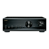
Onkyo A 9555

Onkyo A 9555
41 pages
To Next Page IconTo Next Page
Loading...
A-9555
SERVICE MANUAL
SERVICE MANUAL
INTEGRATED AMPLIFIER
Black, Silver and Golden models
MODEL A-9555
Ref. No. 3920
122005
G UGT, G MGT
G UDT, G MDT
G UGR, G MGR
220-230V AC, 50/60Hz
120V AC, 60Hz
220-230V AC, 50/60Hz
120V AC, 60Hz
230-240V AC, 50Hz
B UDC, B MDC
B UPP, B MPP
120V AC, 60Hz
230-240V AC, 50Hz
S UDC, S MDC
S UPP, S MPP
RC-627S
RC-627S
SAFETY-RELATED COMPONENT
WARNING!!
COMPONENTS IDENTIFIED BY MARK ON THE
SCHEMATIC DIAGRAM AND IN THE PARTS LIST ARE
CRITICAL FOR RISK OF FIRE AND ELECTRIC SHOCK.
REPLACE THESE COMPONENTS WITH ONKYO
PARTS WHOSE PART NUMBERS APPEAR AS SHOWN
IN THIS MANUAL.
MAKE LEAKAGE-CURRENT OR RESISTANCE
MEASUREMENTS TO DETERMINE THAT EXPOSED
PARTS ARE ACCEPTABLY INSULATED FROM THE
SUPPLY CIRCUIT BEFORE RETURNING THE
APPLIANCE TO THE CUSTOMER.
w
w
w
.
x
i
a
o
y
u
1
6
3
.
c
o
m
Q
Q
3
7
6
3
1
5
1
5
0
9
9
2
8
9
4
2
9
8
T
E
L
1
3
9
4
2
2
9
6
5
1
3
9
9
2
8
9
4
2
9
8
0
5
1
5
1
3
6
7
3
Q
Q
TEL 13942296513 QQ 376315150 892498299
http://www.xiaoyu163.com

Other manuals for Onkyo A 9555

Question and Answer IconNeed help?

Do you have a question about the Onkyo A 9555 and is the answer not in the manual?

Onkyo A 9555 Specifications

General IconGeneral
BrandOnkyo
ModelA 9555
CategoryAmplifier
LanguageEnglish

Summary

Safety Warnings and Precautions

Critical Component Identification

Components marked are critical for fire/shock risk. Replace with specified ONKYO parts.

Insulation Measurement Before Return

Measure leakage-current or resistance to ensure insulation before returning to customer.

Service Procedures

Fuse Replacement Guidelines

Instructions for replacing fuses with correct type and rating to prevent fire hazard.

Schematic Diagrams: Power Amplifier

Left Channel Amplifier Circuit

Detailed schematic for the left channel amplifier.

Right Channel Amplifier Circuit

Detailed schematic for the right channel amplifier.

Schematic Diagrams: Pre-Amplifier

Input Selector and Tone Control Circuits

Schematics for input selection and tone control sections.

Schematic Diagrams: Microprocessor

Microprocessor and Control Board Schematics

Detailed schematic of the microprocessor and control boards.

Schematic Diagrams: Phono Equalizer

Phono Equalizer Preamplifier Circuit

Detailed schematic of the phono equalizer stage.

Schematic Diagrams: Power Supply

Power Supply PC Board and AC Input

Schematic of the power supply board and AC input connections.

Related product manuals