IC BLOCK DIAGRAM AND TERMINAL DESCRIPTIONS-19
Q800: AK4588VQ (2/8-Channel Audio CODEC with DIR)-3
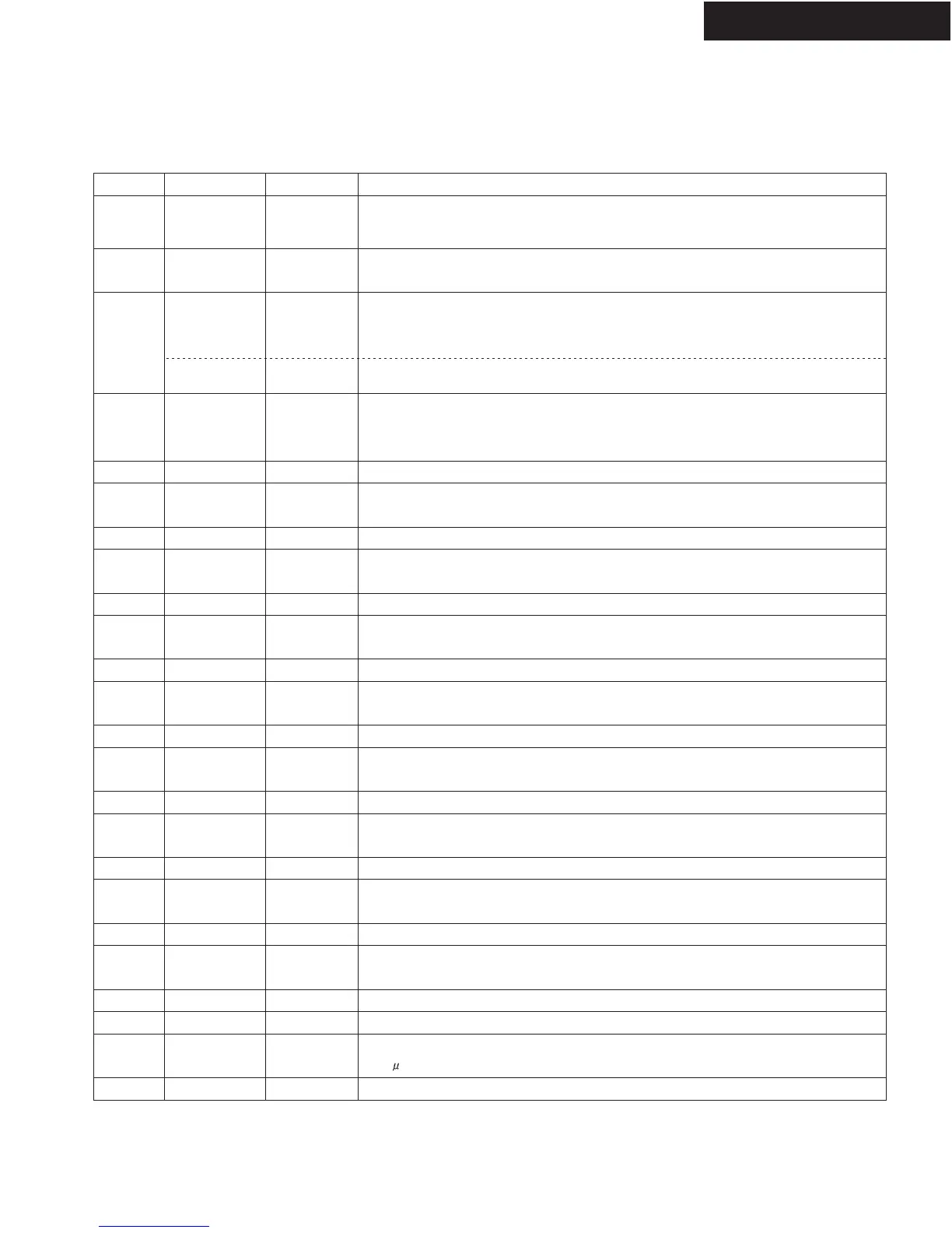
TERMINAL DESCRIPTION
TX-SR502/E/8250/HT-R520
No. Pin Name I/O Function
31
32
33
34
35
36
37
38
39
40
41
42
43
44
45
46
47
48
49
50
51
52
53
54
PDN
MASTER
DZF2
OVF
DZF1
LOUT4
NC
ROUT4
NC
LOUT3
NC
ROUT3
NC
LOUT2
NC
ROUT2
NC
LOUT1
NC
ROUT1
NC
LIN
RIN
VCOM
VREFH
I
I
O
O
O
O
-
O
-
O
-
O
-
O
-
O
-
O
-
O
-
I
I
-
-
Power-Down Mode Pin
When "L", the AK4588 is powered-down, all output pin goes "L", all registers arereset.
When CAD1/0 pins are changed, the AK4588 should be reset by PDN pin.
Master Mode Select Pin
"H": Master mode, "L": Slave mode
Zero Input Detect 2 Pin
When the input data of the group 1 follow total 8192 LRCK cycles with "0" input data,
this pin goes to "H". And when RSTN bit is "0", PWDAN bit is "0", this pin
goes to "H". It always is in "L" when P/S is "H".
Analog Input Overflow Detect Pin
This pin goes to"H" if the analog input of Lch or Rch overflows.
Zero Input Detect 1 Pin
When the input data of the group 1 follow total 8192 LRCK cycles with "0" input data,
this pin goes to "H". And when RSTN bit is "0", PWDAN bit is "0", this pin goes to "H".
Output is selected by setting DZFE pin when P/S is "H".
DAC4 Lch Analog Output Pin
No Connect
No internal bonding.
DAC4 Rch Analog Output Pin
No Connect
No internal bonding.
DAC3 Lch Analog Output Pin
No Connect
No internal bonding.
DAC3 Rch Analog Output Pin
No Connect
No internal bonding.
DAC2 Lch Analog Output Pin
No Connect
No internal bonding.
DAC2 Rch Analog Output Pin
No Connect
No internal bonding.
DAC1 Lch Analog Output Pin
No Connect
No internal bonding.
DAC1 Rch Analog Output Pin
No Connect
No internal bonding.
Lch Analog Input Pin
Rch Analog Input Pin
Common Voltage Output Pin
2.2 F capacitor should be connected to PVSS externally.
Positive Voltage Reference Input Pin, AVDD
 Loading...