TX-L55/LR552
IC BLOCK DIAGRAMS AND DESCRIPTIONS
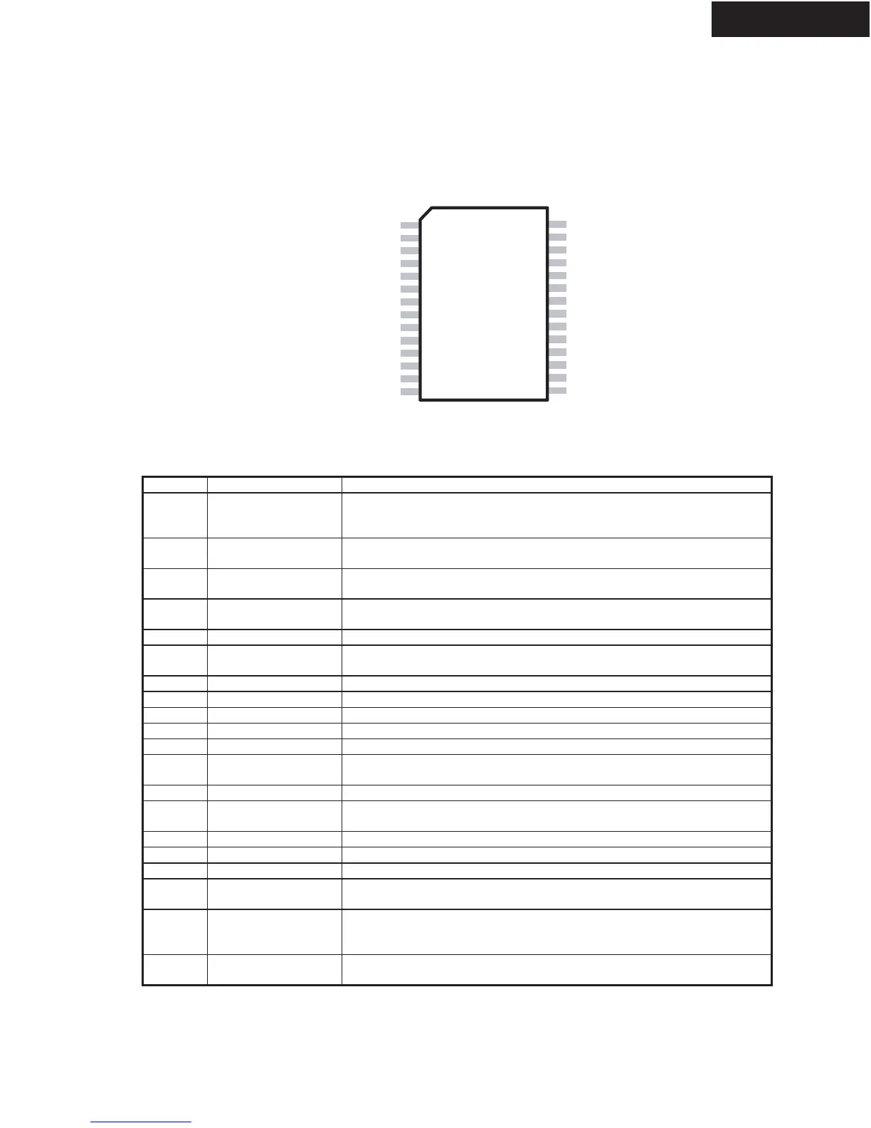
TC2100(Audio Signal Processor)
Pin Connection
REF
VNNSENSE
VPPSENSE
AGND
OAOUT1
MUTE
BBM1
BBM0
OAOUT2
INV2
FBKGND2
OCD2
Y2
Y2B
Y1B
Y1
HMUTE
FBKOUT1
FBKGND1
VPWR
FBKOUT2
DCMP
1
15
14
13
11
10
12
9
8
7
6
5
4
3
2
28-pin SOIC
(Top View)
16
17
18
BIASCAP
INV1
V5
OVRLDB
OCD1
NC
21
20
19
22
23
24
25
26
27
28
Pin Descriptions
Pin Function Description
1 BIASCAP Bandgap reference times two (typically 2.5VDC). Used to set the
common mode voltage for the input op amps. This pin is not capable of
driving external circuitry.
2, 6 FBKGND2,
FBKGND1
Ground Kelvin feedback (Channels 1 & 2)
3 DCMP Internal mode selection. This pin must be grounded for proper device
operation.
4, 7 FBKOUT2,
FBKOUT1
Sw
itching feedback (Channels 1 & 2)
5 VPWR Te
st pin. Must be left floating.
8 HMUTE Logic output. A logic high indicates both amplifiers are muted, due to the
mute pin state, or a “fault”.
9, 12 Y1, Y2 Non-inverted sw
itching modulator outputs.
10, 11 Y1B, Y2B Inverted sw
itching modulator outputs.
13 NC No
connect
14, 16 OCD2, OCD1
Over Current Detect pins.
15 REF Internal bandgap reference voltage; approximately
1.2 VDC.
17 VNNSENSE Negative supply voltage sense input. This pin is used for both over and
under voltage sensing for the VNN supply.
18 OVRLDB A logic low output indicates the input signal has over
loaded the amplifier.
19 VPPSENSE Positive supply voltage sense input. This pin is used for both over and
under voltage sensing for the VPP supply.
20 AGND Analog
Ground.
21 V5 5 Volt power supply
input.
22, 27 OAOUT1, OAOUT2
Input stage output pins.
23, 28 INV1, INV2 Single-ended inputs. Inputs are a “virtual” ground of an inverting opamp
with approximately
2.4VDC bias.
24 MUTE When set to logic high, both amplifiers are muted and in idle mode.
When low (grounded), both amplifiers are fully operational. If left floating,
the device stays in the mute
mode. Ground if not used.
25, 26 BBM1, BBM0 Break-before-make timing control to prevent shoot-through in the output
MOSFET
s.

 Loading...