2. To initialize the unit
This device employs a microprocessor to perform various
functions and operations. If interference generated by an external
power supply, radio wave, or other electrical source results in
accident which causes the specified operations and functions to
operate abnormally.
To perform a result, please follow the procedure below.
1.Press and hold down the VIDEO-1 button, then press the
STANDBY/ON button.
2.After "CLEAR" is displayed, the preset memory and each
mode stored in the memory, such as surround, are
initialized and will return to the factory setting.
3. Unplug the power supply cord.
3. Safety-check out
(U.S.A. model only)
After correcting the original service problem, perform the
following safety check before releasing the set to the customer.
Leakage Current Check
Measure leakage current to a known earth ground(water pipe,
conduit, etc.) by connecting a leakage current tester between
the earth ground and exposed metal parts of the appliance
(input/output terminals, screwheads,metal overlays, etc.).
Plug the power supply cord directly into a 120V AC 60 Hz outlet
and turn Standby switch on. Any current meausred must not
exceed 0.5mA.
1. Replacing the fuses
This symbol located near the fuses indicates that the
fuse used is fast operating type. For continued protection against
fire hazard, replace with same type fuse. For fuse rating refer to
the marking adjacent to the symbol.
Ce symbole indique que le fusible utlise est a rapide.
Pour une protection permanente, n'untiliser que fusibles de
meme type. Ce darnier est la qu le present symbol est
appse.
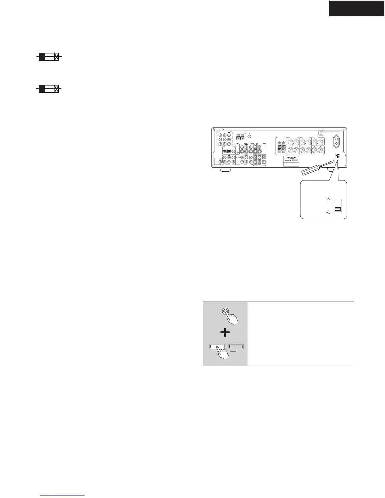
4.Setting the voltage selector (Worldwide models
only)
Worldwide models are equipped with a voltage selector to conform
with local power supplies. Be sure to set this switch to match the
voltage of the power supply in your area before plugging in the unit.
Determine the proper voltage for your area: 220-230 V or 120 V. If
the preset voltage is not correct for your area, insert a screwdriver
into the groove in the switch. Slide the switch all the way to the
upper (120 V) or to the lower (220-230 V), whichever is appropriate.
5.Setting the AM tuning step frequency
(Worldwide models only)
CIRCUIT NO. PART NO.
DESCRIPTION
Note: <D>:120V model only
<O>: Other models except 120V model
<T>: Asian model only for 230V
<R>: Chinese model only
<Q>: Hongkong model only
L
R
R
L
R
L
ANTENNA
FM
75
AM
FRONT
SPEAKERS A
FRONT
SPEAKERS B
SURROUND
SPEAKERS
CENTER
SPEAKER
R
L
SURROUND BACK
SPEAKER
REMOTE
CONTROL
IN
IN
IN
OPTICAL COAXIAL
12
IN
IN
IN
IN
FRONT
SURR
CENTER
SUB
W
OOFER
OUT
OUT
OUT
DIGITAL INPUT
VIDEO 2
VIDEO 1
DVD MONITOR
OUT
VIDEO
S VIDEO
DVD
TAP E
CD
L
R
VIDEO 2
VIDEO 1
SUBWOOFER
PRE OUT
VIDEO 1
/2/3
IN
DVD
IN
COMPONENT VIDEO
Y
P
B
PR
OUT
L
R
SWITCHED
100W MAX.
AC OUTLET
120
V
VOLTAGE
SELECTOR
220-230
V
120
V
VOLTAGE
SELECTOR
220-230
V
If you are using the Worldwide model (i.e., your TX-SR501/
TX-SR501E has a VOLTAGE SELECTOR on the rear
panel), you need to set the AM tuning interval for compati-
bility with AM broadcasts in your particular country. The ini-
tial setting is 9 kHz.
North America: 10 kHz
Other countries: 9 kHz
Note:
All presets are deleted when you change this setting.
To set the AM tuning interval, while
holding down the [TUNER] button,
press the [MEMORY] button.
TUNER
FM MODE
MEMORY
CLEAR
F6901,F6902 252198 or 8A-UL or
252261 8A-T/UL-ST2 <D>
252099 8A-EAK ,Fuse <O>
F901 252166 or 6.3A-UL/T-237 or
252260 6.3A-T/UL-ST2,Fuse <D/T/Q/R>
F902 252076, 3.15A-SE-EAK,
252242 or 3.15A-SE-TL250V or
252276 3.15A-SE-TL250V <O>
F903 252075, 2.5A-SE-EAK,
252241 or 2.5A-SE-TL250V or
252275 2.5A-SE-TL250V,Fuse <O>
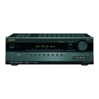
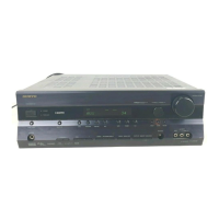
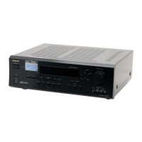
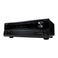
TX-SR501/E
SERVICE PROCEDURES