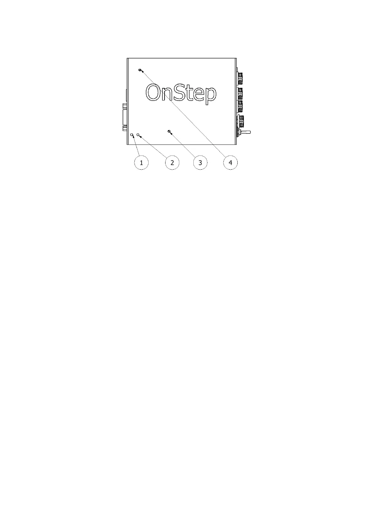
1. Power Supply LED
2. Scope Tracking LED
3. WiFi Status LED
4. CPU Status LED
The controller is equipped with four LEDs, labeled as LED 1, LED 2, LED 3, and
LED 4. These LEDs serve to keep you informed about the controller's status and
activity.
LED 1 indicates the Power Supply status: It should remain illuminated while the
controller is powered on.
LED 2 reflects the scope's tracking status: It flashes while tracking and remains
steadily illuminated otherwise.
LED 3 indicates the status of the WiFi service: A flashing LED signifies that the
WiFi service is being established, while a steadily illuminated LED indicates that
the WiFi service is ready.
4.3 DB9 Encoder Port Connection
The RS232 serial port is a 9 pin modular jack which is mainly used for the telescope
encoders. But it can also be used by other purpose.
Pin 1: Ground
Pin 2: Vsel (5V)
Pin 3: Encoder 1B, encoder 1 input B
Pin 4: Encoder 2B, encoder 2 input B
Pin 5:
Pin 6: Aux3, typically used for a Home SW on RA or Azm but can be used any
purpose (dew heater for instance, on/off switch, etc.). Not wired and not enabled.
10