OPTIMUM
MASCHINEN - GERMANY
Assembly
30 / 11 / 2007 Page 21Assembly Add-on kit D240/D280 ; Version 1.3.3
© 2007
GB
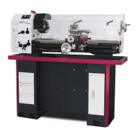
£ Screw the nut (part 22) onto the
shaft elongation.
£ Screw the pulley (part 8) onto the
shaft elongation.
£ In order to be able to adjust the axis
distance more easily later on, screw
the nut and the pulley as much
inside as possible.
Illustr.: 4-36: Nut on shaft elongation
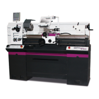
£ Counter the nut on the shaft elonga-
tion with a fork wrench.
£ To facilitate the countering to can
hold fast the handwheel of the com-
pound slide.
Illustr.: 4-37: Counter nut
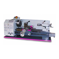
£ Measure the distance from the inner
edge of the pulley to the lathe slide.
£ Have the measured distance firmly
set on the calliper gauge.
Illustr.: 4-38: Measure distance
Spindle elongation
Nut M8x1
Pulley
Fork wrench
SW 14
Pulley
Calliper gauge
Pulley
Lathe slide