Do you have a question about the Optimum OPTIdrill D17 Pro and is the answer not in the manual?
Details important information regarding the manual's content, intended use, and potential deviations.
Explains the meaning and use of various symbols and warning notes included in the manual.
Details the information found on the machine's rating plates, including model and technical data.
Defines categories of hazards, their associated symbols, and potential consequences for safe operation.
Illustrates and explains various warning and informational pictograms used throughout the manual.
Defines the proper and intended applications of the drilling machine and warns against improper use.
Outlines uses of the machine that are considered non-intended and not permissible.
Provides practical tips and precautions to prevent common misuse scenarios during operation.
Details the dangers associated with flying workpieces and necessary precautions.
Highlights inherent risks of the drilling machine due to its operation, such as high speeds and rotating parts.
Stipulates the necessary qualifications and training for operating and maintaining the drilling machine safely.
Outlines the responsibilities and duties of the machine user for safe operation and adherence to instructions.
Provides essential safety precautions to be observed by the operator while the machine is running.
Lists and describes the safety devices integrated into the drilling machine for operator protection.
Details the procedures and intervals for checking the machine's safety features before and during operation.
Explains the function and proper use of the emergency stop button for immediate machine shutdown.
Describes the adjustment and function of the drill chuck guard, a critical safety feature.
Specifies the required personal protective equipment (PPE) for safe operation and special tasks.
Outlines safety precautions and procedures to be followed before and during maintenance activities.
Details the process for safely disconnecting the machine from power and securing it against unauthorized use.
Defines the required intervals for inspecting electrical systems and operating equipment for safe condition.
Specifies the electrical requirements and connection options for the drilling machine models.
Details the motor power ratings for different drilling machine models.
Provides specifications for the maximum drilling diameter in steel for each machine model.
Indicates the throat depth measurement for each drilling machine model.
Presents overall machine dimensions and required operational space for each model.
Details noise emission levels and recommendations for hearing protection.
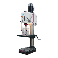
Provides detailed dimensional drawings and measurements specific to the D17 Pro model.
Provides detailed dimensional drawings and measurements specific to the D23 Pro model.
Provides detailed dimensional drawings and measurements specific to the D26 Pro model.
Provides detailed dimensional drawings and measurements specific to the D33 Pro model.
Provides essential notes and warnings regarding the safe transport, installation, and initial setup of the machine.
Highlights common risks and safety precautions associated with moving the machine internally.
Information on receiving the machine, checking for damages, and reporting claims.
Instructions and precautions for safely unpacking the machine and checking delivered contents.
Guidelines for assembling the drilling machine components, emphasizing the need for multiple people.
Step-by-step instructions for attaching the drill column to the machine base.
Detailed procedure for mounting the drilling table support onto the drill column.
Instructions for correctly positioning and securing the drill head onto the main column.
Guides the user on how to properly fit the quick-action drill chuck onto the spindle.
Step-by-step instructions for assembling the safety guard for the drill chuck.
Specifies environmental and workspace requirements for installing the drilling machine.
Details on how to securely fix the drilling machine to the ground for stability and safety.
Critical safety information and procedures for connecting the machine to the electrical supply, especially for 400V.
Procedure for warming up the machine, particularly the spindle, when cold to prevent damage.
Identifies and explains the function of all control buttons, levers, and indicators on the machine.
Details the functions of the ON/OFF buttons and the direction of rotation selector switch.
Step-by-step guide on the correct procedure for starting the drilling machine safely.
Outlines the correct methods for stopping the machine during normal operation and for longer periods.
Explains how to set and use the drill depth stop for precise drilling depth control.
Describes the digital display for monitoring and setting the current drilling depth.
Details how to adjust the drilling table's angle and its implications on carrying capacity.
Guides on how to safely adjust the spindle speed by changing the V-belt configuration.
Provides tables for selecting the appropriate spindle speed based on material and drill bit diameter.
Essential checks and preparations required before commencing any drilling job.
Important safety warnings and operational tips to follow while drilling.
Describes the operation and safety considerations for the spindle sleeve feed mechanism.
Detailed instructions for safely removing and installing drill chucks and bits.
Explains the procedure for clamping and unclamping drill bits using the quick-action chuck.
Steps for correctly fitting the drill chuck onto the spindle using a taper mandrel.
Information on the importance of cooling during drilling and methods for application.
Provides recommended cutting speeds and infeed rates for various materials and drill bit diameters.
Offers a comprehensive table to determine the correct spindle speed based on cutting speed and drill diameter.
Illustrates practical examples of calculating and selecting the correct drilling speed for specific scenarios.
Highlights the critical importance of safety during maintenance and repair activities.
Details the routine inspection and maintenance tasks required for optimal machine performance and longevity.
Instructions for loosening slide rail screws for V-belt tension adjustment.
Specifies the lubrication points and procedures for the drill column and toothed rack.
Guidance on visually inspecting V-belts for wear and porosity.
Procedure for adjusting the tension of the spindle return spring mechanism.
Information on regreasing the spindle toothing and recommended lubricants.
Specifies the requirements for electrical inspection of the machine's components.
Information on how to request assistance from authorized customer service technicians for repairs.
States the copyright protection and reserved rights for the manual's content.
Provides a glossary of technical terms used throughout the operating manual.
Outlines the terms and conditions for liability claims and warranty coverage for the product.
Provides guidelines for proper storage of the machine and its components to prevent damage.
Offers advice on environmentally friendly disposal methods for the machine and its packaging.
Instructions for safely decommissioning the machine to prevent misuse and environmental harm.
Guidelines for the professional and statutory compliant disposal of electrical and electronic parts.
Information on how to dispose of products at designated collection points for recycling.
Information on how customers can provide feedback or report issues to the manufacturer.
Identifies the manufacturer/distributor and provides their contact and location details.
Specifies the product's designation, type, and trade names.
Lists the EU directives and harmonized standards that the product complies with.
Instructions on how to order spare parts, specifying the information required.
Provides contact details for the spare parts hotline for inquiries and orders.
Provides contact information for the service hotline for technical assistance and support.
Illustrations and part numbers for the D17Pro model, aiding in identification of replacement parts.
Illustrations and part numbers for the D23Pro model, aiding in identification of replacement parts.
Illustrations and part numbers for the D26Pro model, aiding in identification of replacement parts.
Illustrations and part numbers for the D33Pro model, aiding in identification of replacement parts.
Detailed diagram and parts list for the drill chuck protection assembly.
Electrical wiring diagram for the 230V version of the D17Pro and D23Pro drilling machines.
Electrical wiring diagram for the 400V version of the D23Pro, D26Pro, and D33Pro drilling machines.
| Model | OPTIdrill D17 Pro |
|---|---|
| Category | Drill |
| Drilling capacity in steel (diameter) | 16 mm |
| Spindle taper | MT 2 |
| Number of speeds | 12 |
| Projection | 180 mm |
| T-slot size | 14 mm |
| Drill head tiltable | ±45° |
| Power Source | 230 V |