SURETY PAGING RELAY
PRIORITY CHANNEL AND PROGRAM
CHANNEL.
This connects when the PRIORITY channel priority contact is activated.
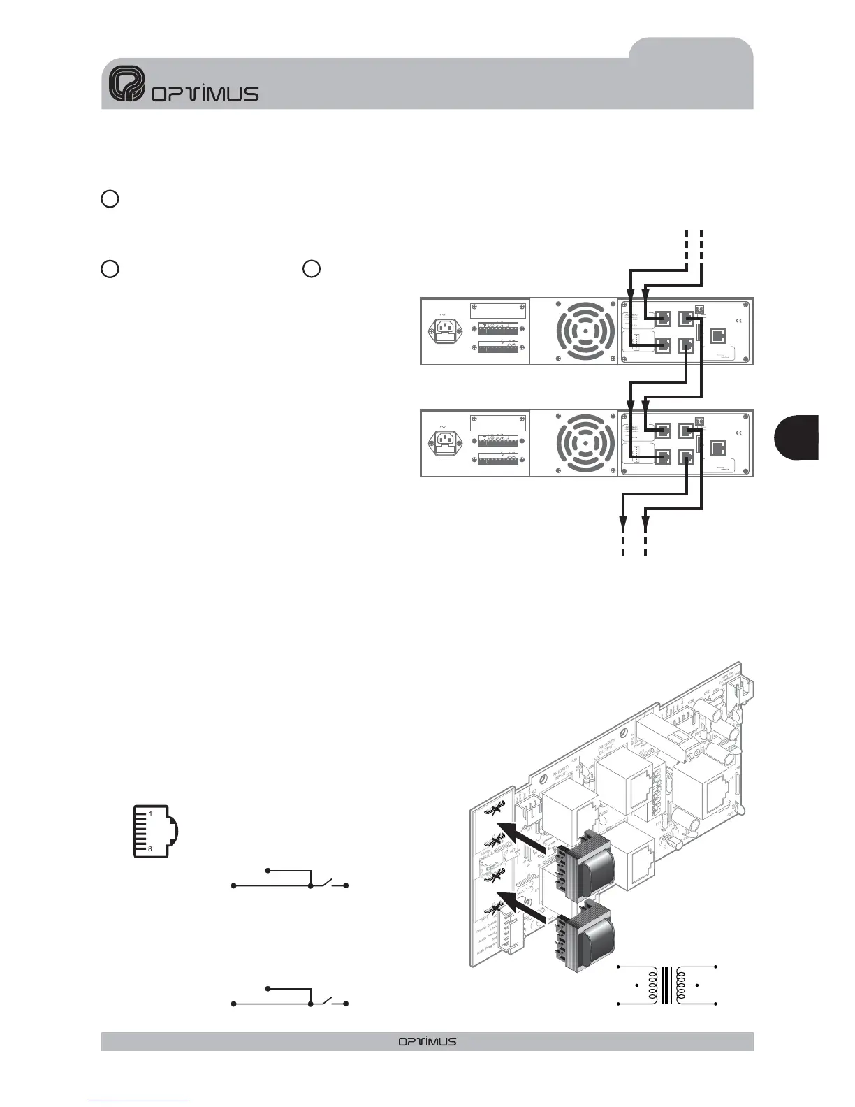
The two input channels (PROGRAM and
PRIORITY) use four RJ45 connectors which
are connected in pair and parallel formation.
This means that they can provide a signal for
other boosting stages (see figure 4).
The amplifier should be connected using an
STP Cat-5 cable (see figure 5). This cable is
renowned for its very low impedance, which
means that it allows for an exceptionally flat
frequential response even over long distances
and obviously meets with CMRR and crosstalk
requirements for analogic audio applications.
The signal inputs are not balanced and have a
sensitivity of 0 dBU (775mV).
Pin no. 3 provides a voltage of 24 V.d.c., which
can be used to power low consumption
devices.The maximum current supplied is 200
mA in each channel.
In the PRIORITY channel, when pin no.6 is linked to pin no.8 the priority system and the surety paging relay are
activated (see figure 2, no.9).The priority control can be transmitted to other boosting stages through pin no.6 of
the PRIORITY OUTPUT connector, depending on the position of dipswitches 7 and 8
(See section 3.REARVIEW, no.12).
Another option is to connect a symmetric transformer (T700) to these inputs and
remove the J1 and J2 jumpers for the program input and the J3 and J4 jumpers
for the priority input. The transformers should be connected as is
indicated in figure 6.
Fuse
OUTPUTS
050V
FAIL
SURETY
PAGING
70V
100V
16
Ω
8
Ω
4
Ω
24V
FAN
POWER
SUPPLY
230V
50/60 Hz
INPUT/OUTPUT CONTACTS
1
234
5
6
7
89
PRIORITY
CTRL. INPUT
GND
PRIORITY
INPUT
PRIORITY
OUTPUT
PROGRAM
INPUT
PROGRAM
OUTPUT
ON OFF
POWER AMPLIFIER
240W RMS(312W IHF)
UP-247
Engineered in EU (Spain)
Made inChina
OPTIMUS S.A.
PRI-PRO RJ CONNECTION
6. PRIORITY
8.
METAL
SHIELD
GND
(WHEN BALANCED)
7
8
6
5
3
2
1
DIPSWITCH CONFIGURATION
ON OFF
PRI-PRO
LINK
SHIELD-GND
LINK
7. Priorityctrl. in
6. AudioC
5. AudioH
4. Priorityin
8. Priorityctrl. out
3. Priorityout
2. Programin
1. Programout
SURVEILLANCE
SURVEILLANCE RJ CONNECTION
1. OSC IN
2. NC
3. OSC OUT 1
4. PROTECT
5. OSC OUT 2
6. PRI OUT
7. +24VDC OUTPUT
8.
METAL
SHIELD
GND
24V
FAIL
OUTPUTS
0 50V 70V 100V
4
Ω
8
Ω
16
Ω
SURETY PAGING
Pin number 1: SIGNAL H
Pin number 2: SIGNAL C (if the input is balanced)
Pin number 3: +24VDC
Pin number 6: PRIORITY contact
Pin number 8:
Shield
Pin number 1: SIGNAL H
Pin number 2: SIGNAL C (if the input is balanced)
Pin number 3: +24VDC
Pin number 8:
Shield
PRIORITY CHANNEL CONNECTION
PROGRAM CHANNEL CONNECTION
GND
GND
1
8
Figure 6
Figure 5
N.C. N.C.
600 Ohm 600 Ohm
T-700
9
10
11
Figure 4
PRIORITY CHANNEL
INPUT TRANSFORMER
J4
J3
J2
J1
PROGRAM CHANNEL
INPUT TRANSFORMER
17
Eng
ENGLISH
UP-367, UP-247, UP-127 and UP-67 Version 1.0
AMPLIFIERS UP-367, UP-247, UP-127 and UP-67